18-BC53D2-6 13
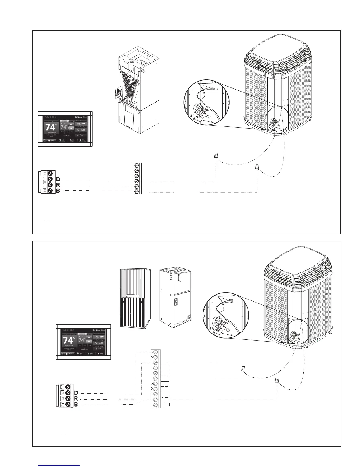
11.2 Low Voltage Hook-up Diagrams
Communicating
Comfort Control
TAM8 Communicating
Air Handler
Communicating Outdoor Unit
Neatly bundle all low voltage
wires behind the service
valve cover as shown.
Field wiring
Brown
Blue
Brown
Blue
Red
B - Blue
D - Note 2
O
D
R
B
Y1
Y2
Note 1
Fully Communicating System
Notes:
1. In communicating mode, unused terminals are non-functional. Do not use.
2. “D” is the data line. Installer to select a wire color.
3. If a 3rd party condensate overflow switch is installed, it should be wired in series with R to the thermostat
or connected to the External Switch terminals on the AFC. See External Switch wiring section in the air
handler Installer’s Guide.
4. For 24 VAC Outdoor equipment, accessory BAYCC24VK01A must be ordered separately.
Communicating
Comfort Control
Communicating Outdoor Unit
Neatly bundle all low voltage
wires behind the service
valve cover as shown.
Brown
Blue
Brown
Blue
Red
B - Blue
D - Note 2
Note 3
Note 1
Comm. Variable Speed
Furnace or Air Handler
W1
W2
W3
G
Y2
B
O
BK
D
Y1
R
Fully Communicating System
Notes:
1. In communicating mode, unused terminals are non-functional. Do not use.
2. “D” is the data line. Installer to select a wire color.
3. To connect optional devices (such as a float switch), wire in series from indoor unit “R” to Comfort Control “R”.
 Loading...