18-BC53D2-6 3
When mounting the outdoor unit on a roof, be
sure the roof will support the unit’s weight.
Properly selected isolation is recommended to
alleviate sound or vibration transmission to the
building structure.
Section 2. Unit Location Considerations
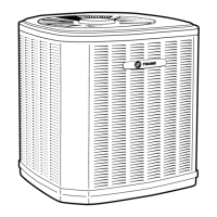
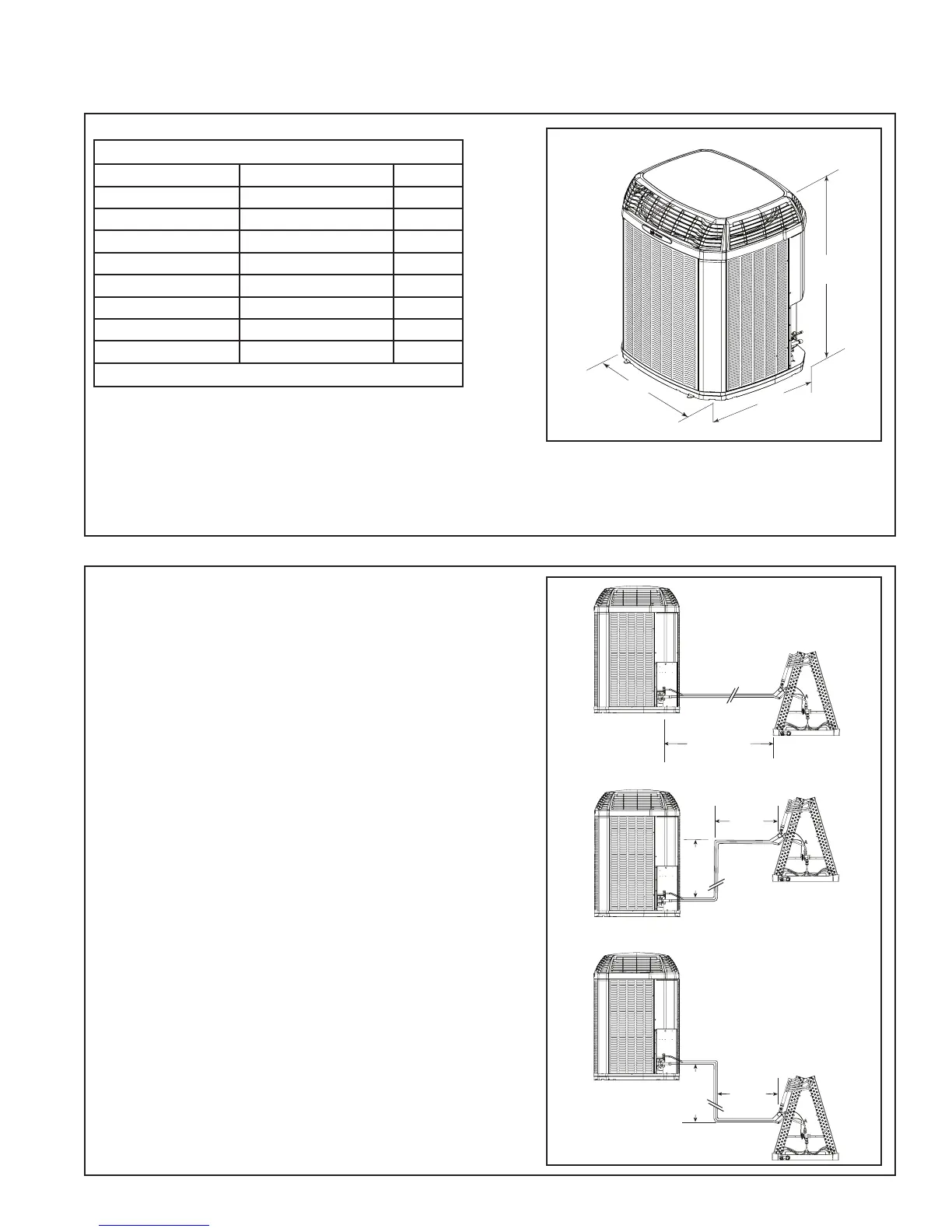
2.1 Unit Dimensions and Weight
2.2 Refrigerant Piping Limits
Unit Dimensions and Weight
Models H x D x W (in)
Weight* (lb)
4TTZ0024A
54 x 34 x 37 335
4TTZ0036B
54 x 34 x 37 335
4TTZ0048A/B
54 x 34 x 37 420
4TTZ0060A
54 x 34 x 37 420
4TWZ0024A
54 x 34 x 37 340
4TWZ0036B
54 x 34 x 37 345
4TWZ0048A/B
54 x 34 x 37 430
4TWZ0060A
54 x 34 x 37 430
* Weight values are estimated (uncrated).
25’
Max
Line
Lift
Standard
Line Set
60’ Max
Line Length
25’
Max
Line
Lift
35’ Max
Line
Length
35’ Max
Line
Length
1. The maximum length of refrigerant lines
from outdoor to indoor unit should NOT
exceed sixty (60) feet.
2. The maximum vertical change should not
exceed twenty five (25) feet*.
3. Service valve connection diameters are
shown in Table 5.1.
NOTE: For line lengths greater than sixty (60)
feet, Refer to Refrigerant Piping Application
Guide, SS-APG006-EN or Refrigerant Piping
Software Program, 32-3312-03 (or latest revi-
sion).
Table 2.1
*
*
*
Restricted to maximum vertical change of 25 ft.
 Loading...