12 18-BC90D1-4A-EN
Section 9. Evacuation
9.1 Evacuate the Refrigerant Lines and Indoor Coil
Important: Do not open the service valves until
the refrigerant lines and indoor coil leak check
and evacuation are complete.
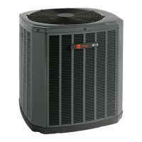
STEP 1 - Evacuate until the micron gauge reads
no higher than 350 microns, then close off the
valve to the vacuum pump.
STEP 2 - Observe the micron gauge. Evacuation
is complete if the micron gauge does not rise
above 500 microns in one (1) minute.
Once evacuation is complete blank off the
vacuum pump and micron gauge, and close the
valves on the manifold gauge set.
1 MIN.
Section 10. Service Valves
10.1 Open the Gas Service Valve
0350
Microns
ON
OFF
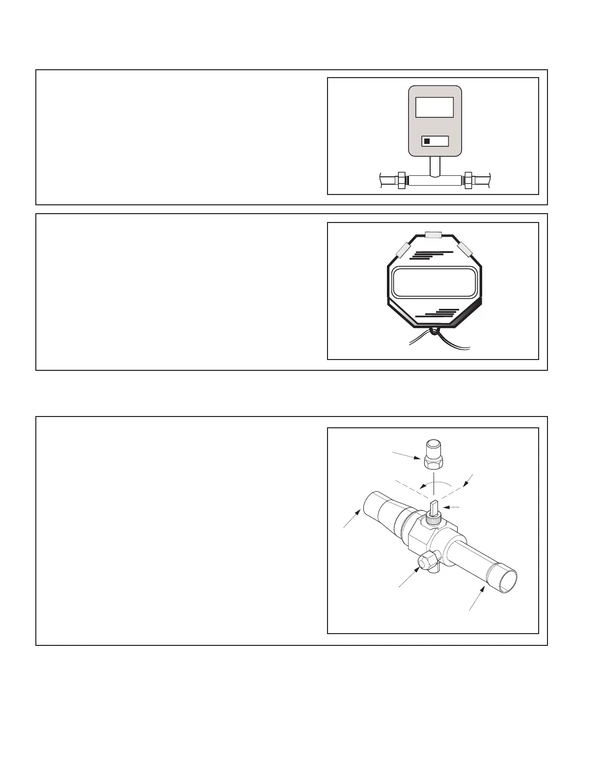
CAP
COUNTERCLOCKWIS
FOR FULL OPEN
POSITION
VALVE STEM
GAS LINE CONNECTION
UNIT SID
E
PRESSURE TAP PORT
Important: Leak check and evacuation must be
completed before opening the service valves.
NOTE: Do not vent refrigerant gases into the
atmosphere.
STEP 1 - Remove valve stem cap.
STEP 2 - Using an adjustable wrench, turn valve
stem 1/4 turn counterclockwise to the fully open
position.
STEP 3 - Replace the valve stem cap to prevent
leaks. Tighten finger tight plus an additional 1/6
turn.
 Loading...