Installer's
Guide
C.
RECOMMENDATION
If a coil is part
of
the total system installation, use the Installer's
Guide packaged with the furnaces, outdoor sections, and ther-
mostat for
physically installing those components.
A CAUTION °
Caution: This
col/Is
pressurized with 8-12
psig
of
dry
air.
Do
not
stand
directly
In
front
of
the
coil
connections when
removing sealing plugs.
If
no
pressure
is
released,
check
for
leaks.
..
'
D.
FURNACE
IN
UPFLOW POSITION
1.
UPFLOW
COIL CONVERSION: While
not
required, optional
removal
of some coil components
will
maximize airflow
efficiency.
a.
Remove the coil by sliding the coil out
of
the coil
enclosure.
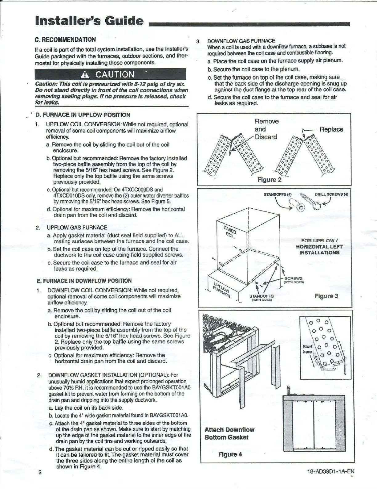
b.
Optional
but
recommended:
Remove
the
factory installed
two-piece baffle assembly
from
the top of the coil by
removing the
5/16"
hex
head screws. See Figure 2.
Replace only the top baffle using the same screws
previously provided.
c.
Optional
but
recommended:
On
4TXCC009DS
and
4TXCD01
0DS
only,
remove
the
(2)
outer
water
diverter
baffles
by
removing
the
5/16"
hex
head
screws.
See
Figure
5.
d.
Optional for
maximum
efficiency:
Remove
the horizontal
drain pan
from
the coil and discard.
2.
UPFLOW
GAS
FURNACE
a. Apply gasket material (duct seal field supplied) to ALL
mating surfaces between the furnace and the coil case.
b.
Set the coil case on top
of
the furnace. Connect the
ductwork to the coil case using field supplied screws.
c.
Secure the coil case to the furnace and seal for air
leaks as required.
E.
FURNACE
IN
DOWNFLOW
POSfnON
1.
DOWN
FLOW
COIL CONVERSION: While not required,
optional
removal
of
some
coil components
will
maximize
airflow efficiency.
a. Remove the coil
by
sliding the coil out of the coil
enclosure.
b.
Optional but recommended: Remove the factory
installed two-piece baffle assembly from the top of the
coil by removing the 5/16" hex head screws. See Figure
2.
Replace only the top baffle using the same screws
previously provided.
c.
Optional for maximum efficiency: Remove the
horizontal drain pan from the coil and discard.
2.
DOWNFLOW
GASKET
INSTALLATION
(OPTIONAL)
:
For
unusually
humid
applications
that
expect
prolonged
operation
above
70%
RH
, it is
recommended
to
use
the
BAYGSKT001AO
gasket
kit to
prevent
water
from
forming
on
the
bottom
of
the
drain
pan
and
dripping
into
the
supply
ductwork
.
2
a.
Lay the coil on its back side.
b.
Locate
the
4"
wide
gasket
mate
ria
l
found
in
BAYGSKT001AO.
c.
Attach
the
4"
gasket
material to three sides of the bottom
of
the
drain
pan
as
shown.
Make
sure to start
by
matching
up
the edge of
the
gasket material to the inner edge of
the
drain
pan by
the
coil fins
and
working outwards.
d.
The gasket material can be cut or ripped easily so that
it can
be tailored to fit. The gasket material must cover
the three sides along the entire length of the
coil as
shown in Figure
4.
3. DOWNFLOW
GAS
FURNACE
When
a
coil
is
used
with
a
downflow
furnace,
a
subbase
is
not
required
between
the
coil
case
and
combustible
flooring.
a. Place the coil case
on
the furnace supply air plenum.
b.
Secure the coil case to the plenum.
c.
Set the furnace on top of the coil case, making sure
that the back side
of
the discharge opening
is
snug up
against the
~uct
flange
at
the top rear
of
the coil case.
d.
Secure the coil case to the furnace and seal for air
leaks as required .
Attach Downflow
Bottom
Gasket
Figure 4
Remove
and
Figure 2
FOR
UPFLOW/
HORIZONTAL LEFT
INSTALLATIONS
Figure 3
18-
AD39D1
-1A-
EN
 Loading...