18-BB41D1-1C-EN
9
Review Location and Recommendation Information
HHoorriizzoonnttaall AAiirrffllooww UUnniittss
1. Location of the unit must allow service clearance
around it to ensure adequate serviceability,
maximum capacity, and peak operating efficiency.
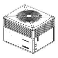
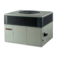
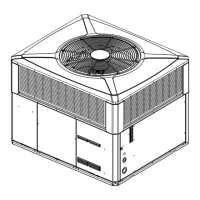
2. These units are designed for outdoor installation.
They may be installed directly on a slab, wood
flooring, or on Class A, B, or C roof covering
material. The discharge air from the condenser fans
must be unrestricted for a minimum of 3 feet above
the unit.
3. Check the handling facilities to ensure the safety of
personnel and the unit(s).
4. The unit must be mounted level for proper drainage
of water through the drain holes in the base pan.
5. The unit should not be exposed to direct roof water
runoff.
6. Flexible duct connectors must be of a flame
retardant material. All duct work outside of the
structure must be insulated and weatherproofed in
accordance with local codes.
7. Holes through exterior walls or roof must be sealed
in accordance with local codes.
8. All fabricated outdoor ducts should be as short as
possible.
CClleeaarraanncceess
1. The recommended clearances for single-unit
installations are illustrated in “Determine Unit
Clearances,” p. 7.
2. Any reduction of the unit clearances indicated in
these figures may result in condenser coil
starvation or the recirculation of warm condenser
air. Actual clearances, which appear to be
inadequate should be reviewed with a local
engineer.
3. See the unit’s nameplate for the absolute minimum
clearance between the unit and any combustible
surfaces.
DDoowwnn AAiirrffllooww UUnniittss
1. Location of the unit must allow service clearance
around it to ensure adequate serviceability,
maximum capacity, and peak operating efficiency.
2. Refer to the Installation section for instruction on
converting the supply and return airflow covers to
down airflow.
3. The field assembled Roof Mounting Curb
(BAYCURB050A or BAYCURB051A) or a field
fabricated curb should be in place before the unit is
hoisted to the roof top.
The Roof Mounting Curb (frame) must be installed
on a flat, level section of the roof (maximum of 1/4"
per foot pitch) and provide a level mounting surface
for the unit. Also, be sure to provide sufficient
height above the roof to prevent water from
entering the unit.
4. Be sure the mounting curb spans structural
members (trusses) of the roof, thereby providing
sufficient support for the weight of the unit, the
curb, the duct(s), and any factory or field installed
accessories.
5. The unit must be mounted level for proper drainage
of water through the drain holes in the base pan.
6. Be sure the hole in the structure for the ducts is
large enough to accommodate the fabricated ducts
and the insulation surrounding them. Flexible duct
connectors must be of a flame retardant material.
All duct work outside of the structure must be
insulated and weatherproofed in accordance with
local codes.
7. Holes through exterior walls or roof must be sealed
in accordance with local codes.
8. These units are design certified for outdoor
installation. They may be installed directly on a
slab, wood flooring, or on Class A, B, or C roof
covering material. The discharge air from the
condenser fans must be unrestricted for a minimum
of 3 feet above the unit.
9. Check the handling facilities to ensure the safety of
personnel and the unit(s).
CClleeaarraanncceess
1. The recommended clearances for single-unit
installations are illustrated in “Determine Unit
Clearances,” p. 7.
2. Any reduction of the unit clearances indicated in
these figures may result in condenser coil
starvation or the recirculation of warm condenser
air. Actual clearances, which appear to be
inadequate should be reviewed with a local
engineer.
3. See the unit’s nameplate for the absolute minimum
clearance between the unit and any combustible
surfaces.
 Loading...