20
18-BB35D1-16B-EN
DDeemmaanndd DDeeffrroosstt OOppeerraattiioonn
During the heating cycle, the outdoor coil may require
a defrost cycle which is determined by the demand
defrost control (DFC). This control continuously
measures the outdoor coil temperature (CBS) and the
outdoor ambient temperature (ODS-B) and calculates
the difference or delta-T measurement. When the
calculated delta-T is met, the demand defrost control
(DFC) opens the circuit to the outdoor fan motor (ODM)
and energizes the switch-over valve (SOV), placing the
unit in the cooling mode to defrost the outdoor coil (on
SCROLL bearing units only, the control will stop the
compressor for a minimum of thirty (30) seconds). The
outdoor coil temperature sensor (CBS) terminates the
defrost cycle, or it times off after twelve (12) minutes in
defrost, the (DFC) energizes the outdoor fan motor
(ODM) and twelve seconds later de-energizes the
(SOV), which returns the unit to the heating mode.
Supplementary electric heat, if provided, is brought on
to control indoor temperature during the defrost cycle.
During this defrost cycle the indoor fan will run at the
speed designated for 2nd stage cooling.
DDeeffrroosstt CCoonnttrrooll
The demand defrost control measures heat pump
outdoor ambient temperature with a sensor located
outside the outdoor coil. A second sensor located on
the outdoor coil is used to measure the coil
temperature. The difference between the ambient and
the colder coil temperature is the difference or delta-T
measurement. This delta-T measurement is
representative of the operating state and relative
capacity of the heat pump system. Measuring the
change in delta-T determines the need for defrost. The
coil sensor also senses outdoor coil temperature for
termination of the defrost cycle.
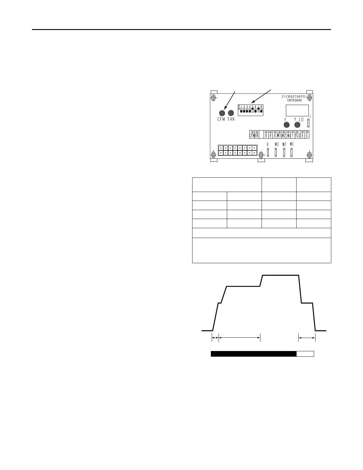
EECCMM FFaann MMoottoorr AAddjjuussttmmeennttss
If the airflow needs to be increased or decreased, see
the Airflow Table in the Service Facts. Information on
changing the speed of the blower motor is in the
Blower Performance Table.
Blower speed changes are made on the ICM Fan
Control mounted in the control box. The ICM Fan
Control controls the variable speed motor.
There is a bank of 8 dip switches located at the upper
left side of the board. The dip switches work in pairs to
match the cooling/heat airflow (CFM/TON), Fan off-
delay options, and electric heat airflow adjustment. The
switches appear as shown in Figure 8, p. 20.
Figure 8. ECM Fan Control
CFM
SELECTION
LIGHT
DIP
SWITCHES
Table 11. Cooling Off - Delay Options
SWITCH SETTNGS SELECTION NOMINAL
AIRFLOW
5 - OFF 6 - OFF NONE SAME
5 - ON 6 - OFF 45 SECONDS 100%*
5 - OFF 6 - ON 1.5 MINUTES 50%
5 - ON 6 - ON ** 50 -100%
* - This setting is equivalent to the BAY24X045 relay benefit.
** - This ENHANCED MODE selection provides a ramping up and
ramping down of the blower speed to provide improved comfort,
quietness, and potential energy savings. The graph below show
the ramping process.
OFF OFF
50%
80%
100% if necessary
50%
Dehumidify
Fast Coil Cooling
and Heating
Efficiency
7.5
minutes
3
minutes
1
minute
FAN OPERATION (CFM)
COMPRESSOR OPERATION ON
OFF
as required
UUnniitt SSttaarrttuupp
 Loading...