30
18-EB32D1-1E-EN
3. Check the temperature rise during furnace
operation to insure that it falls within the range
specified on the unit's nameplate.
4. If the temperature rise noted is outside of the
specified limits, adjust the indoor air flow to cause
the temperature rise of the heat exchanger to fall
within the required range.
FFlluueeHHooooddaannddCCoommbbuussttiioonnBBlloowweerrCClleeaanniinngg
CCAAUUTTIIOONN
FFiirreeoorrEExxpplloossiioonn!!
FFaaiilluurreettooffoolllloowwpprrooppeerrpprroocceedduurreessccaannrreessuullttiinn
ppeerrssoonnaall iinnjjuurryyoorrsseevveerreeeeqquuiippmmeennttddaammaaggee
NNeevveerruusseeccoommbbuussttiibblleecclleeaanniinnggfflluuiiddssoonna
annyyppaarrtt
oofftthheeffuurrnnaaccee..
Before each heating season, the flue should be
inspected for signs of flaking rust and soot deposits.
DDiirrttyyfflluueesssshhoouullddbbeecclleeaanneeddbbyyqquuaalliiffiieeddsseerrvviiccee
ppeerrssoonnnneell OONNLLYY using the following procedure:
1. Turn the comfort control to OOFFFF. Turn the main
power disconnect OOFFFF. Turn the manual gas valve
OOFFFF.
2. Remove the flue hood and the CONTROL/HEAT
access panel.
3. Remove the combustion blower assembly from the
flue box. Remove the flue box and the flue
restrictors.
4. Remove all wires from the gas valve while carefully
noting their locations.
5. Disconnect the gas supply line from the valve.
6. Remove the manifold retaining screws and pull the
burner-manifold assembly from the heat
exchanger.
7. Remove the inlet turbulators being careful not to
break or damage them.
8. Wipe the flue box and flue baffles clean with a
clean, dry cloth.
9. Replace all gaskets with new ones.
10. Replace all damaged or broken turbulators with
new ones.
11. Reassemble the unit by reversing Steps 2 through 7
above. Take care that all gaskets seat properly.
12. Check all wires for correct installation by referring
to the unit’s electrical wiring diagram in the
SERVICE FACTS.
13. Leak test all gas line connections with a soap and
water solution or the equivalent.
14. Re-install the CONTROL/HEAT access panels and
the flue hood.
15. Visually inspect the unit to ensure that the airflow
opening for combustion is not obstructed.
16. Follow the start-up procedure on page 22 to place
the unit back in service.
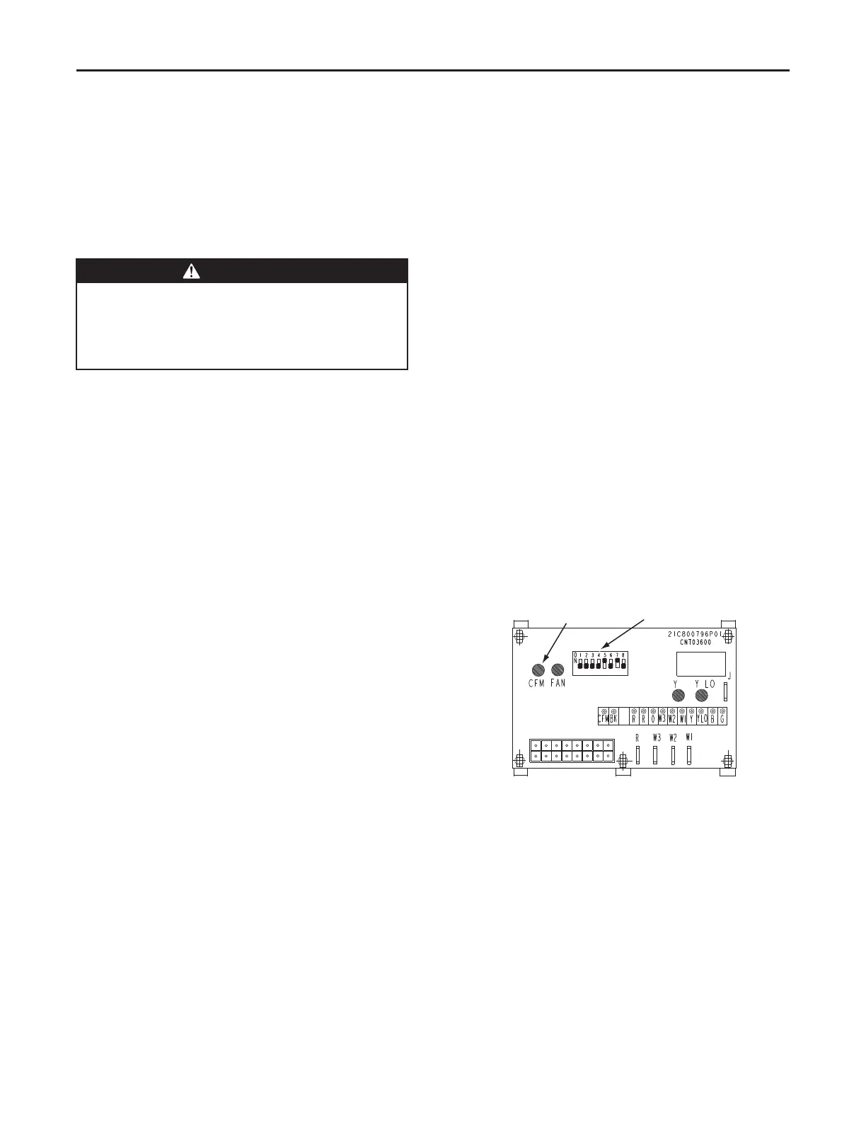
ECM Fan Motor Adjustments
If the airflow needs to be increased or decreased, see
the Airflow Table in the SERVICE FACTS. Information
on changing the speed of the blower motor is in the
Blower Performance Table. Blower speed changes are
made on the ECM Fan Control mounted in the control
box. The ECM Fan Control controls the variable speed
motor. There is a bank of 8 dip switches, (See Figure 23
below), located on the board. The dip switches work in
pairs to match the cooling/heat airflow (CFM/TON), Fan
off-delay options and electric heat airflow adjustment.
The switches appear as shown in the ECM Fan Control
Figure.
Figure 16. ECM Fan Control
CFM
SELECTION
LIGHT
DIP
SWITCHES
SSeeqquueenncceeooffOOppeerraattiioonn
 Loading...