22
18-EB32D1-1E-EN
Electrical Wiring
WWAARRNNIINNGG
II NNSSTTAALLLLAATTIIOONNWWAARRNNIINNGG——HHIIGGHH
VVOOLLTTAAGGEEMMOOVVIINNGGPPAARRTTSS!!
FFaaiilluurreettooffoolllloowwtthhiissWWaarrnniinnggccoouullddrreessuullttiinn
pprrooppeerrttyyddaammaaggee,, sseevveerreeppeerrssoonnaall iinnjjuurryy,, oorr
ddeeaatthh..
BBooddiillyyiinnjjuurryyccaannrreessuullttffrroommhhiigghhvvoollttaaggee
eelleeccttrriiccaall ccoommppoonneennttss,, ffaassttmmoovviinnggffaannss,, aanndd
ccoommbbuussttiibblleeggaass.. FFoorrpprrootteeccttiioonnffrroommtthheessee
ii nnhheerreenntthhaazzaarrddssdduurriinnggiinnssttaallllaattiioonnaannddsseer
rvviicciinngg,,
tthheemmaaiinnggaassvvaallvveemmuussttbbeettuurrnneeddooffffaannddtthhee
eelleeccttrriiccaall ssuuppppllyymmuussttbbeeddiissccoonnnneecctteedd.. IIff
ooppeerraattiinnggcchheecckkssmmuussttbbeeppeerrffoorrmmeeddw
wiitthhtthheeuunniitt
ooppeerraattiinngg,, iittiisstthheetteecchhnniicciiaann’’ssrreessppoonnssiibbiilliittyyttoo
rreeccooggnniizzeetthheesseehhaazzaarrddssaannddpprroocceeeeddssaaffeellyy..
NNoottee:: This unit is factory wired for 230V. See wiring
diagram for 208V conversion.
EElleeccttrriiccaall CCoonnnneeccttiio
onnss
Electrical wiring and grounding must be installed in
accordance with local codes or, in the absence of local
codes, with the National Electrical Code ANSI/NFPA 70,
Latest Revision.
DDiissccoonnnneeccttSSwwiittcchh
Provide an approved weatherproof disconnect within
close proximity and wwiitthhiinnssiigghhttoofftthheeuunniitt..If
disconnect must be mounted to the cabinet, the
location shown in Figure 13, p. 23 should be the only
one considered.
OOvveerrCCuurrrreennttPPrrootteeccttiioonn
The branch circuit feeding the unit must be protected
as shown on the unit's rating plate.
PPoowweerrWWiirriinngg
The power supply lines must be run in weather-tight
conduit to the disconnect and into the side of the unit
control box. Provide strain relief for all conduit with
suitable connectors.
Provide flexible conduit supports whenever vibration
transmission may cause a noise problem within the
building structure.
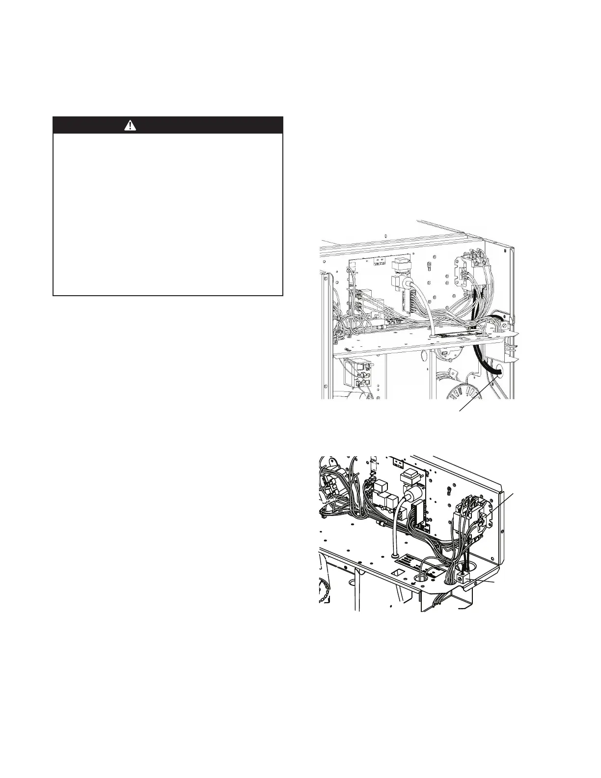
1. Remove the Control/Heat access panel. Pass the
power wires through the Power Entry hole in the
end of the unit. Figure 11, p. 22
2. Connect the high voltage wires to the appropriate
contactor terminals. Single phase units use a two
(2) pole contactor and three phase units use three
(3) pole contactor. Connect the ground to the
ground lug on the chassis. See Figure 12, p. 22.
Be sure all connections are tight.
GGRROOUUNNDDIIN
NGG:: TTHHEEUUNNIITTMMUUSSTTBBEEEELLEECCTTRRIICCAALLLLYY
GGRROOUUNNDDEEDDIINNAACCCCOORRDDAANNCCEEWWIITTHHLLOOCCAALLCCOODDEESS
OORRTTHHEENNAATTIIOONNAALLEELLEECCTTRRIICCCCOODDEE..
NNoottee:: Unit must be grounded for ignitor to operate
properly. Gas pipe to unit is not an adequate
ground. Ground the unit internally as provided.
See wiring diagram for location in .
Figure 11. Power Wiring
Run power supply lines through weather-tight
conduit and secure to unit with strain relief.
Figure 12. Power Connections
 Loading...