18-EB32D1-1E-EN
23
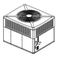
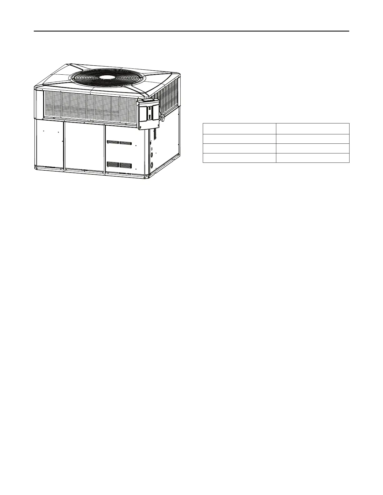
Figure 13. Mounted Disconnect Location
CCoonnttrrooll WWiirriinngg((CCllaassssIIII))
Low voltage control wiring should not be run in conduit
with power wiring unless Class 1 wire of proper voltage
rating is used. Route the thermostat cable or equivalent
single leads of No. 18 AWG colored wire from the
thermostat subbase terminals through the rubber
grommet on the unit. See Unit Clearance Graphics for
the control entry (24V Entry) location. Make
connections as shown on the unit wiring diagram.
Do not short thermostat wires since this will damage
the control transformer.
Refer to Table 11, p. 23 for recommended wire sizes
and lengths for installing the unit thermostat. The total
resistance of these low voltage wires must not exceed
one (1) ohm. Any resistance in excess of 1 ohm may
cause the control to malfunction because of the
excessive voltage drop.
Table 11. Thermostat Wire Size and Max. Length
:LUH 6L]H
0D[LPXP /HQJWK
TThheerrmmoossttaattHHeeaattAAnnttiicciippaattoorr
Set the heat anticipator of the thermostat to equal the
amperage draw of the gas valve
II mmppoorrttaanntt:: UUppoonnccoommpplleettiioonnooffwwiirriinngg,, cchheecckkaallll
eelleeccttrriiccaall ccoonnnneeccttiioonnss,, iinncclluuddiinnggffaaccttoorryy
wwiirriinnggwwiitthhiinntthhe
euunniitt..
Make sure all connections are tight. Replace and secure
all electrical box covers and access panels before
leaving the unit or turning on the power to the unit.
EElleeccttrriiccaall WWiirriinngg
 Loading...