© Trane 2019 All rights reserved. 18-AD37D1-1-EN
Installer’s Guide
D. RECOMMENDATION
If a coil is part of the total system installation, use the In-
staller’s Guide packaged with the furnaces, outdoor sections,
and thermostat for physically installing those components.
Caution: This coil is pressurized with 8-12 psig of dry air.
Do not stand directly in front of the coil connections when
removing sealing plugs. If no pressure is released, check
for leaks.
E. FURNACE IN UPFLOW POSITION
1. UPFLOW COIL CONVERSION: While not required,
optional removal of some coil components will maximize
airflow efficiency.
a. Remove the coil by sliding the coil out of the coil
enclosure.
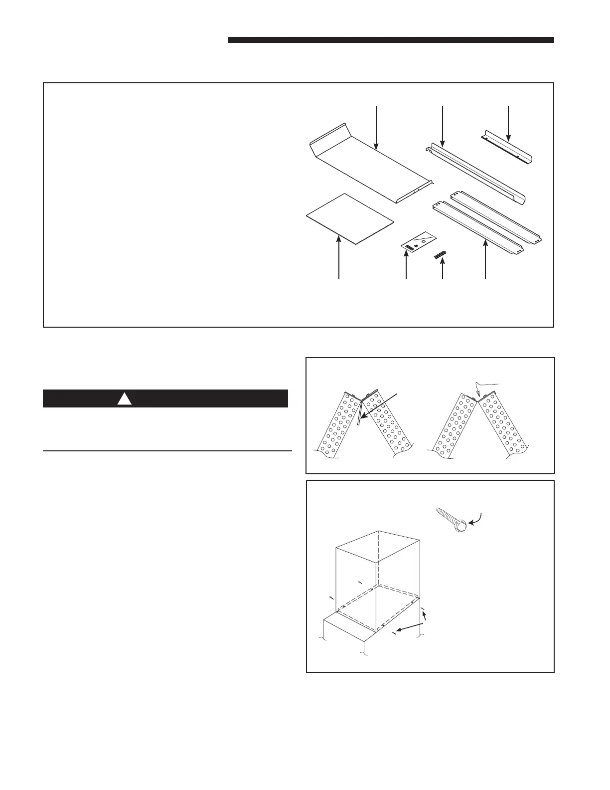
b. Optional but recommended: Remove the factory in-
stalled two-piece baffle assembly from the top of the coil
by removing the 5/16” hex head screws. See Figure 2.
Replace only the top baffle using the same screws previ-
ously provided.
c.
Optional for maximum efficiency: Remove the horizon-
tal drain pan from the coil and discard.
2. UPFLOW GAS FURNACE
a. Apply gasket material (duct seal field supplied) to ALL
mating surfaces between the furnace and the coil case.
b. Set the coil case on top of the furnace. Connect the duct-
work to the coil case using field supplied screws.
c. Secure the coil case to the furnace and seal for air leaks
as required.
FOR UPFLOW / HORIZONTAL
LEFT
INSTALLATIONS
Figure 3
Figure 2
UPFLOW
FURNACE
CASED
COIL
SCREWS
(BO
1-1/2” MAXIMUM
FIELD SUPPLIED
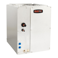
C. ACCESSORY PARTS
Open and inspect the contents shipped with the coil for
damage or missing items.
Each kit will contain:
Item Qty Description
1 1 Splash Guard
2 1 Splash Guard Bracket
3 1 Hairpin Baffle
4 1 Installer's Guide
5* 1 Orifice Kit
6 1 Screws
7** 2 Downflow Baffles
* Item not shipped with A4MXC/D4260
** Shipped with A4MXC4260, A4MXD4260 only
1
4 5 6 7
2 3
Secure alignment between the furnace and coil cabinet
using field-provided self-tapping screws (see Figure 3). For
S-series furnaces, bend furnace duct flanges outward for
cased coil alignment. Drill screws into furnace duct flange
though clearance alignment holes located near bottom of
coil cabinet.
The coil is always placed downstream of the fur-
nace airflow.
 Loading...