4 18-CD29D1-11
Installer’s Guide
Do NOT install the furnace in a corrosive or contaminated
atmosphere.
LOCATION AND CLEARANCES
The location of the furnace is normally selected by the ar-
chitect, the builder, or the installer. However, before the
furnace is moved into place, be sure to consider the follow-
ing requirements:
1. Is the location selected as near the vent and as central-
ized for heat distribution as practical?
2. Do all clearances between the furnace and enclosure
equal or exceed the minimums shown in the Table 1.
3. Is there sufficient space for servicing the furnace and
other equipment? A minimum of 24 inches front ac-
cessibility to the furnace must be provided. Any access
door or panel must permit removal of the largest com-
ponent.
4. Are there at least 3 inches of clearance between the fur-
nace front panel and any closed panel or door provided?
5. Are the ventilation and combustion air openings large
enough and will they remain unobstructed? If outside
air is used, are the openings set 12" minimum above
the highest snow accumulation level?
6. Allow sufficient height in supply plenum above or below
the furnace to provide for cooling coil installation if the
cooling coil is not installed at the time of this furnace
installation.
7. A furnace shall be installed so electrical components are
protected from water.
8. If the furnace is installed in a residential garage, it
must be installed so that the burners and the ignition
source are located not less than 18 inches (46 cm) above
the floor and the furnace must be located or protected
to avoid physical damage from vehicles.
IMPORTANT:
The furnace must be installed level. The only allowable varia-
tion would be slightly to the left and/or forward in upflow instal-
lations or slightly toward the front in horizontal installations.
This is necessary for proper condensate drainage.
NOTE:
On upflow 5 or 6 ton airflow models where the airflow re-
quirement exceeds 1800 CFM - Models will require return
air openings and filters on: (1) both sides; or (2) one side
and the bottom; or (3) just the bottom.
EXPLOSION HAZARD!
PROPANE GAS IS HEAVIER THAN AIR AND MAY
COLLECT IN ANY LOW AREAS OR CONFINED SPAC-
ES. IN ADDITION, ODORANT FADE MAY MAKE THE
GAS UNDETECTABLE EXCEPT WITH A WARNING
DEVICE. IF THE GAS FURNACE IS INSTALLED IN A
BASEMENT, AN EXCAVATED AREA OR A CONFINED
SPACE, IT IS STRONGLY RECOMMENDED TO CON-
TACT A GAS SUPPLIER TO INSTALL A GAS DETECT-
ING WARNING DEVICE IN CASE OF A GAS LEAK.
NOTE: The manufacturer of your furnace does NOT test
any detectors and makes no representations regarding
any brand or type of detector.
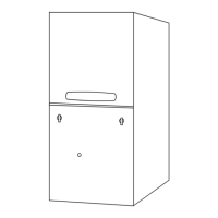
UPFLOW
FURNACE
CASED
COIL
SCREWS
(BOTH SIDES)
STANDOFFS
(BOTH SIDES)
STANDOFFS (4)
DRILL SCREWS (4)
FOR VERTICAL
INSTALLATIONS:
1
UPFLOW INSTALLATION
Standoffs and screws (See Figure 1) are included with
the cased coils for attachment to the furnace. There
are clearance alignment holes near the bottom of the
coil wrapper. Drill screws are used to engage the fur-
nace top flanges. The standoff is inserted into the
cabinet alignment hole. The drill screws are inserted
through the standoffs then screwed into the furnace
flange.
The coil is always placed downstream of the furnace
airflow.
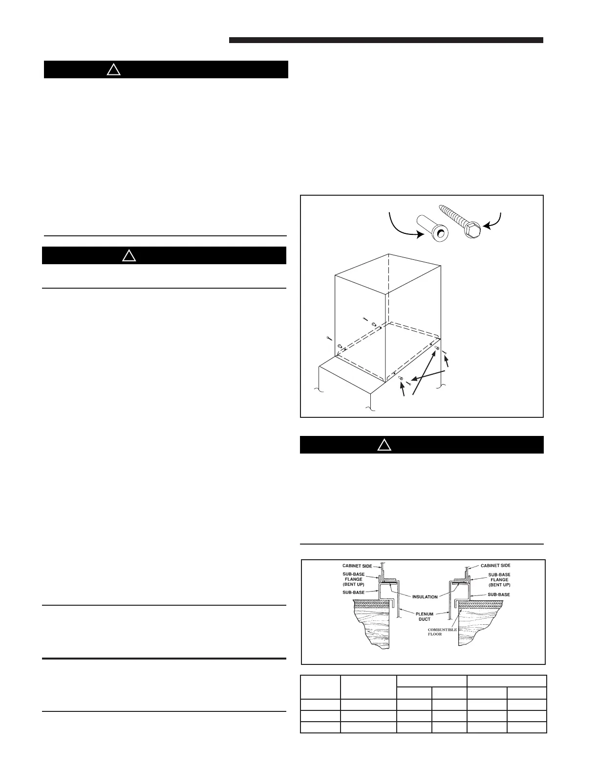
DOWNFLOW INSTALLATIONS
FIRE HAZARD
Do NOT install the furnace directly on carpeting, tile
or other combustible material other than wood floor-
ing. For vertical downflow application, subbase (BAY-
BASE-205) must be used between the furnace and
combustible flooring. When the downflow furnace is
installed vertically with a cased coil, a subbase is not
required.
Required floor opening:
SUBBASE CROSS SECTION
TABLE 1
CABINET
WIDTH
RETURN
DUCT WIDTH
FLOOR OPENING PLENUM OPENING
"A" "B" "C" "D"
17-1/2" 16-1/4" 16-5/8" 20-1/8" 15-5/8" 19-3/8"
21" 19-3/4" 20-1/8" 20-1/8" 19-1/8" 19-3/8"
24-1/2" 23-1/4" 23-5/8" 20-1/8" 22-5/8" 19-3/8"
2
 Loading...