16
CXRC-SVX01J-EN
Figure 15. Isolator Locations for CCRC/CIRC 50-60
Ton
Leveling the Unit
Before tightening down the mounting bolts, level the
unit carefully. Use the unit base rail as a reference.
Level the unit to within 1/4” over its entire length. Use
shims if not using adjustable isolators.
Refrigerant Piping
General Refrigerant Recommendations
Liquid Line Components
Indoor portion of liquid line should include service
valve, charging valve, thermal expansion valve, sight
class/moisture indicator, filter drier and solenoid valve.
(Others as required by job specifications.) If the CCRC/
CIRC is coupled with either SCRF/SIRF or SCRG/SIRG,
these components are factory installed in the indoor
unit, except filter driers which are ship-with, for field
installation. CCRC/CIRC units also include a charging
valve.
• Sight glass/moisture indicators aid in
troubleshooting, charging and servicing the
system. Locate between filter drier and expansion
valve.
• Filter-driers are provided for field installation.
Locate near evaporator.
• Solenoid valves should be located near the
evaporator.
Discharge Line Components
Indoor portion of discharge line should include access
valve and check valve. If the CCRC/CIRC is coupled with
either SCRF/SIRF or SCRG/SIRG, these components are
factory installed on the indoor unit. Install other
discharge line components as required by job
specifications (hot gas mufflers, pipe anchors, oil traps,
etc.) to provide proper system operation, prevent
excessive vibration and assure proper oil return to the
compressor. Also recommended are discharge shutoff
valves in each hot gas line near the condenser to
facilitate refrigerant storage in the condenser during
service procedures. When optional discharge line ball
valves are present in the indoor section, installation of
field supplied discharge line access valves near the
indoor unit may aid in installation and service.
NNOOTTIICCEE
CCoommpprreessssoorr DDaammaaggee!!
FFaaiilluurree ttoo ffoollllooww iinnssttrruuccttiioonnss bbeellooww ccoouulldd rreessuulltt iinn
ccoommpprreessssoorr ddaammaaggee..
TToo pprreevveenntt ppoossssiibbllee rreeffrriiggeerraanntt ddrraaiinn bbaacckk iinnttoo
ccoommpprreessssoorr dduurriinngg ooffff ccyyccllee,, iiff nnoo ddiisscchhaarrggee cchheecckk
vvaallvvee iiss uusseedd,, ddrroopp ddiisscchhaarrggee lliinnee wweellll bbeellooww
ccoommpprreessssoorr ddiisscchhaarrggee lleevveell bbeeffoorree bbeeggiinnnniinngg
vveerrttiiccaall rriissee..
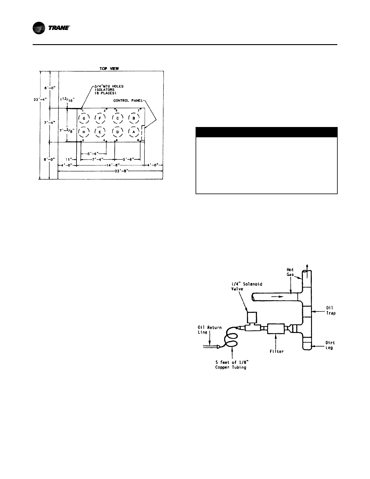
NNoottee:: See Figure 16, p. 16 for a typical refrigerant
piping configuration that may be used in place of
a double riser system (not recommended). This
arrangement assures adequate oil return to the
suction line, even at partial load conditions.
Refer to Trane Air Conditioning Manual for more
specific piping recommendations.
Figure 16. Typical Configuration for Constant Drain
Oil Trap
Refrigerant Piping Recommendation
Isolate refrigerant lines from the building to prevent
transferring line vibration to the structure. Do not
secure lines rigidly to the structure at any point, as this
will defeat the unit isolation system.
IInnssttaallllaattiioonn -- MMeecchhaanniiccaall
 Loading...