CVHE-SVX02M-EN
51
Installing the Tracer AdaptiView
Display
During shipment, the Tracer® AdaptiView™ display is
boxed, shrink-wrapped, and located behind the control
panel. The display must be installed at the site.
IImmppoorrttaanntt:: For best results, Trane, or an agent of
Trane, must install the Tracer
®
AdaptiView
™
display and display arm.
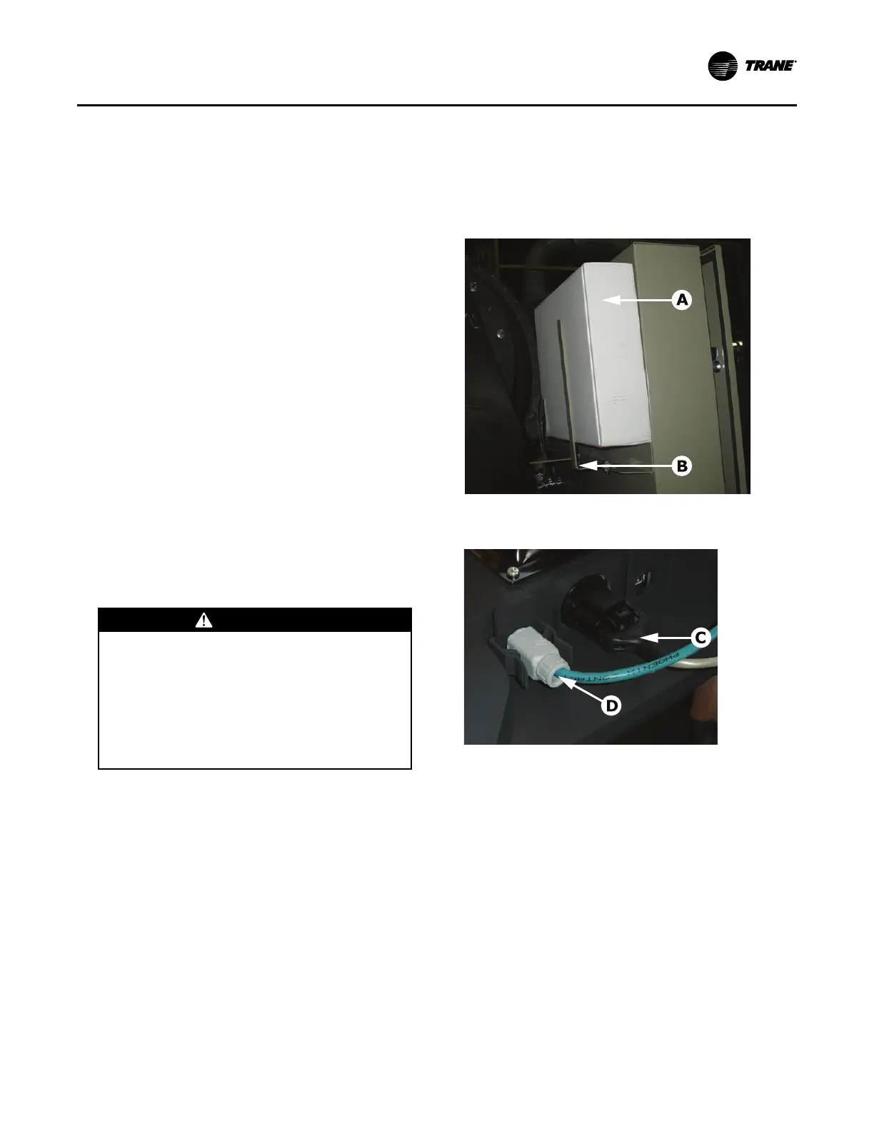
1. Unwrap the control panel and display arm. Locate
the box containing the Tracer® AdaptiView™
display behind the control panel (labeled A in
Figure 33, p. 51).
2. After the box containing the display has been
removed, remove the shipping bracket from the
back of the control panel (labeled B in Figure 33, p.
51).
3. Remove the display from the box.
NNoottee:: Screws are M4 (metric size 4), 6 to 8 mm long,
and are shipped with the display.
4. Plug the power cable (labeled C in Figure 34, p. 51)
and the Ethernet cable (labeled D in Figure 34, p.
51) into the bottom of the display.
NNoottee:: Both cables are already present and extend
from the end of the display arm.
5. Adjust the Tracer® AdaptiView™ display support
arm so the base plate that attaches to the display is
horizontal.
CCAAUUTTIIOONN
TTeennssiioonn iinn DDiissppllaayy SSuuppppoorrtt AArrmm!!
FFaaiilluurree ttoo ffoollllooww iinnssttrruuccttiioonnss bbeellooww ccoouulldd
rreessuulltt iinn uunneexxppeecctteedd mmoovveemmeenntt ooff tthhee sspprriinngg--
llooaaddeedd ssuuppppoorrtt aarrmm wwhhiicchh ccoouulldd rreessuulltt iinn mmiinnoorr
ttoo mmooddeerraattee iinnjjuurryy..
EEnnssuurree tthhaatt tthhee ssuuppppoorrtt aarrmm iiss iinn tthhee ffuullll
uupprriigghhtt ppoossiittiioonn wwhheenn rreemmoovviinngg tthhee TTrraacceerr
AAddaappttiiVViieeww ddiissppllaayy ffrroomm tthhee ssuuppppoorrtt aarrmm..
NNoottee:: Review “Adjusting the Tracer AdaptiView
Display Arm,” p. 52 before attaching the
display as some adjustments may be
required prior to attaching the display to the
support arm base.
6. Position the Tracer® AdaptiView™ display—with
the LCD screen facing up—on top of the display
support arm base plate.
NNoottee:: Ensure the Trane logo is positioned so that it
will be at the top when the display is attached
to the display support arm.
IImmppoorrttaanntt:: Use care when positioning the Tracer
®
AdaptiView
™
display on top of the support
arm base plate and do NOT drop the
display.
7. Align the four holes in the display with the bolt
holes in the display support arm base plate.
8. Attach the Tracer® AdaptiView™ display to the
display support arm base plate (labeled E in Figure
35, p. 52) using the M4 (metric size 4) screws
referenced in “Step 3,” p. 51.
Figure 33. Tracer®® AdaptiView™™ shipping location
Figure 34. Power cable and Ethernet cable
connections
IInnssttaallllaattiioonn:: CCoonnttrroollss
 Loading...


