11
CVHE-SVN02D-EN
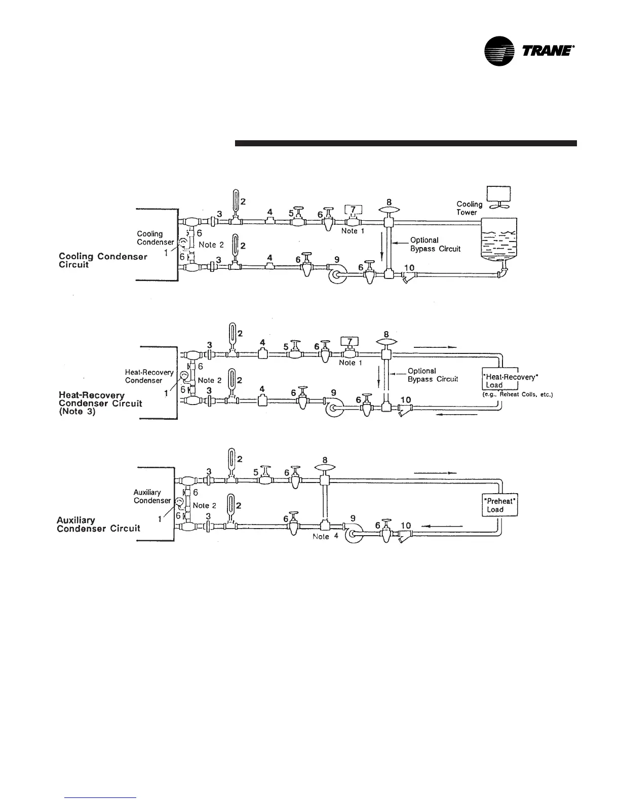
Water Piping
Notes:
1. The Flow Switch 5S2 (Item 7 in Legend of Components) may be installed in either the entering or leaving leg of the chilled water circuit.
2. It is recommended to pipe a single gauge between entering and leaving pipes.
3. Some type of field-supplied temperature control device may be required to regulate the temperature of the heat-recovery condenser water circuit. For application
recommendations, see Trane Application Manual, “AM-FND-8”, titled “Heat-Recovery Engineering Seminar”.
4. Install a bypass valve system to avoid circulating water through the auxiliary shell when the unit is shut down.
5. On multiple pass condensers, entering condenser water must enter at the lowest nozzle.
Legend of Field-Supplied and Installed Components
1. Pressure Gauge
2. Thermometer(s) (If field supplied)
3. Union(s) or Flanged Connection(s)
4. 1/2" [13 mm] NPT Couplings
5. Balancing Valve
6. Gate (Isolation) Valve(s) or Ball Valve(s)
7. Condenser Water Flow Switch
8. 3-Way Valve (Optional)
9. Condenser Water Pump
10. Strainer
Figure 4. Typical condenser water piping circuits
 Loading...


