CVHE-SVN02D-EN
12
Water Piping
Table 1. Evaporator water piping connection sizes
Nominal Pipe Size (inch/mm)
1 Pass 2 Pass 3 Pass
EVSZ Inch mm Inch mm Inch mm
032 8 219.1 6 168.3 5 141.3
050 10 273.0 8 219.1 6 168.3
080 12 323.4 10 273.0 8 219.1
142 16 406.4 12 323.9 10 273.0
210 16 406.4 14 355.6 12 323.9
250 16 406.4 14 355.6 12 323.9
Note: EVSZ = Evaporator Shell Size; S = Short Shell, L = Long Shell, E = Extended Shell
Table 2. Condenser water piping connection sizes
Nominal Pipe Size (inch/mm)
2 Pass
CDSZ Inch mm
032 6 168.3
050 8 219.1
080 10 273.0
142 12 323.9
210 14 355.6
250 14 355.6
Note: CDSZ =Condenser Shell Size; S = Short Shell, L = Long Shell, E = Extended Shell
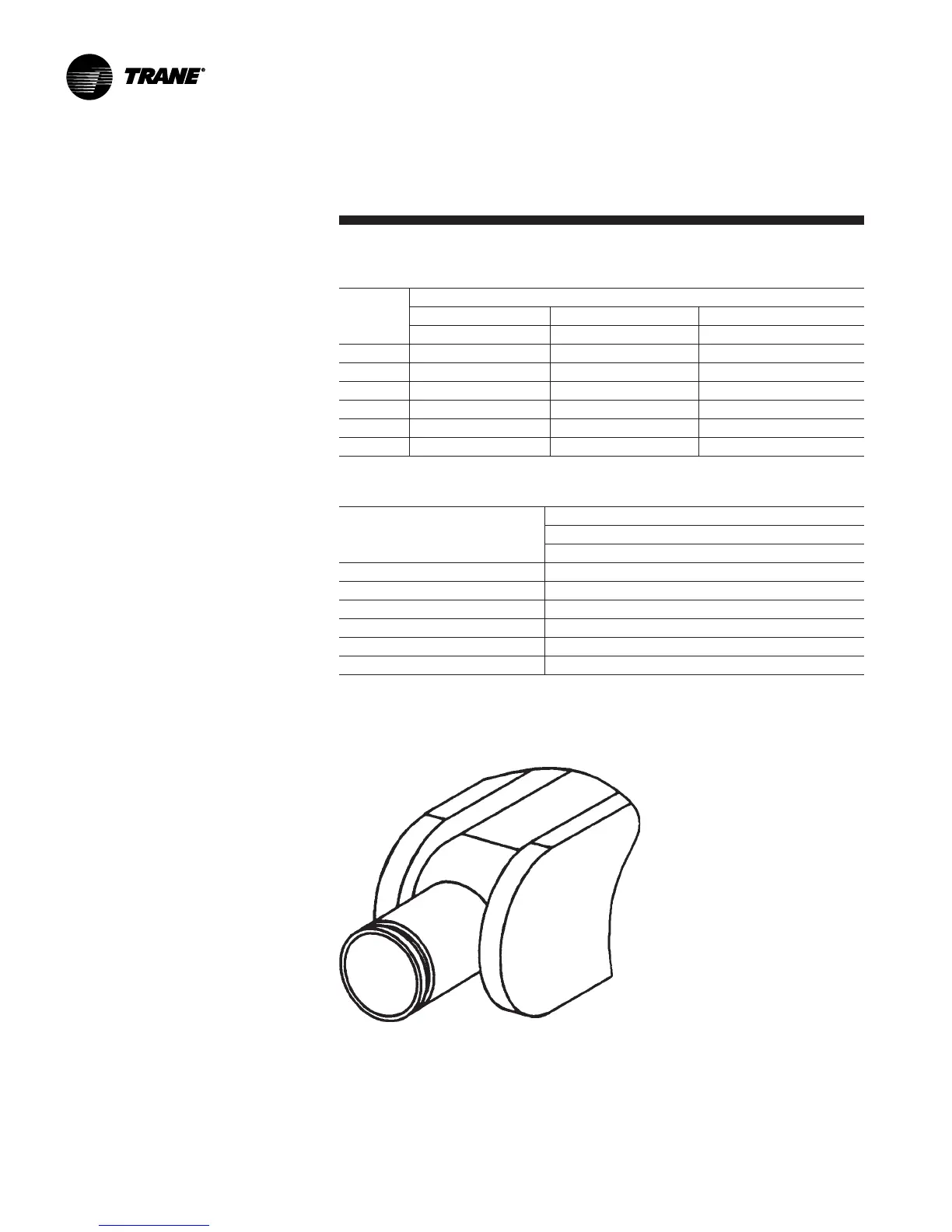
Figure 5. Typical CVHE grooved pipe connection
Water Piping Connections
For CVHEs beginning with design
sequence “1D,” all units (except
those with 032 through 050
condenser shells with 150 psig [1035
kPa] non-marine water boxes) use
cut-groove end NSP Victaulic style
pipe connections. All CVHGs
beginning with “1A” and later
design sequences. All CVHF units,
“A” and later design sequences, use
grooved-pipe connections. See
Figure 5.
Piping joined using grooved type
couplings, like all types of piping
systems, requires proper support to
carry the weight of pipes and
equipment. The support methods
used must eliminate undue stresses
on joints, piping and other
components; allow movement
where required, and provide for any
other special requirements (i.e.,
drainage, etc.).
 Loading...


