17
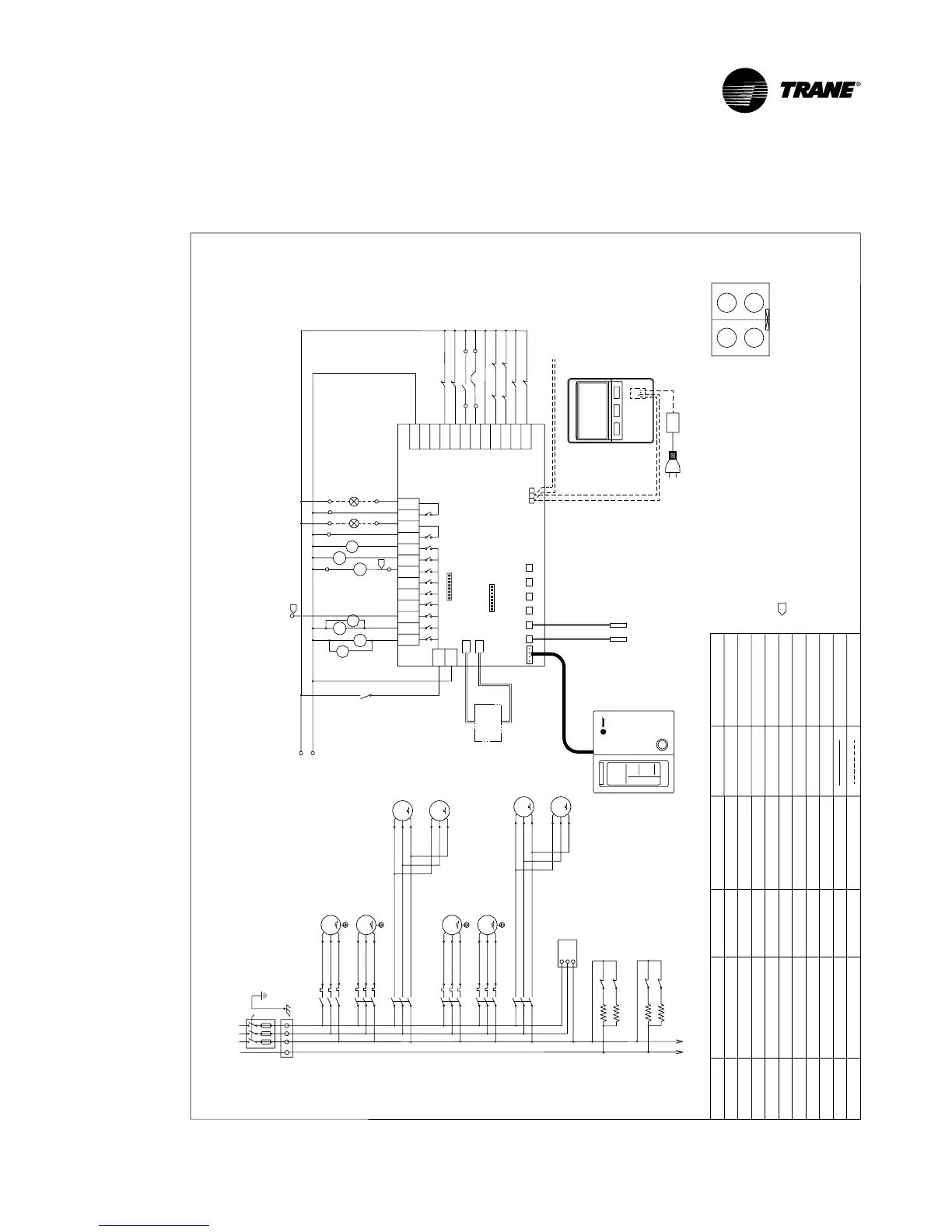
Wiring Diagram
The following wiring diagrams are for reference only. The accompanied wiring diagrams shall prevail.
B
A
C
(11)
(14)
BA
+12VGND
CN1
ABG
Chiller's Water Pump Contactor
Fan Motor Contactor
Compressor Start Contactor
Description
Name
Description
Name
Description
Name
Compressor
Crankcase Heater
Plate Heat Exchanger Heater
Water Circuit Based
Electrical Heating Control
Water Pump
Alarm Output/Input
Fan Motor
Common Neutral Line
Energy Saving/
2- Way Valve Interlock
Run Output/Input
Outer Cool/Heat Pump Setting
Compressor Overload/Overheat
Fan Motor Overheat
Water Pump Overload
Flow Switch
High Pressure Switch
Low Pressure Switch
Terminal Board
Phase Sequence Controller
4 Way Valve
Field Wiring
Factory Wiring
Water flow switch need connect between 15 and U
DIP setting (sw1,sw2) according to IOM
MC1-1
312 710
U
N
3
N
RUN
MP
N
MF1
FLOW
LP1
OV-COMP2
OV-COMP1
HP1
OV-FAN
OV-PUMP
LP2
HP2
N-COM
C/H
COMP2
M/FAN2
H/FAN1
A-HAT
4WV2
HE/EV1
4WV1
PUMP
COMP1
RUN_OUT
RUN_IN
AL_OUT
AL_IN
EN-SAVE
CON1
CON2
MF1
8 11
AL
N
TH2
TH1
TH3
TH4
TH5
TH6
690134120001
C/H
RUN-OUT/IN
EN-SAVE
N-COM
AL-OUT/IN
H/FAN
PUMP
A-HAT
HT/EV1
COMP
CCH
MF
MC
4WV
TB
HP
LP
OVP
OVF
MP
FS
OVC
MF2
MF2
MC1-2
MC2-1
MC2-2
15
16
Wiring Diagram
(connected network and module mode)
RFS
Reserved control signal for controlling water pump and heating
Pump Overload Switch(close) Connect 16 and U
Note:
Compressor Location
ADC_OD_C01
power
Water Inlet Sensor
Water Outlet Sensor
Control panel
(Option)
TO CONTROL WIRING
CCH1-2
CCH1-1
32
31
MC1-2
MC1-1
MC1-2
COMP 1-2
3 ~
M
(L2)
(L3)
MC1-1
COMP 1-1
3 ~
M
TB1
380Vac 3N~50Hz
N
U
M
FAN
MOTOR 1-2
3 ~
220Vac
RFS
M
FAN
MOTOR 1-1
3 ~
OVC1- 1
OVC1- 2
CGAJ1305 (N Type)
(L2)
(L3)
MC2-2
(L1)
COMP 2-2
3 ~
M
(L1)
(L2)
(L3)
MC2-1
COMP 2-1
3 ~
M
M
FAN
MOTOR 2-2
3 ~
M
FAN
MOTOR 2-1
3 ~
OVC2-1
OVC2-2
CCH2-2
CCH2-1
34
33
MC2-2
MC2-1
N
U
(L1)
BK
YL
BK
YL
(L2)
(L3)
(L1)
(L2)
(L3)
(L1)
(L2)
(L3)
(L1)
(L2)
(L3)
(L1)
(L2)
(L3)
(L1)
(Two Compressors)
Microprocessor Control Board
Transformer
BK
YL
BK
YL
L
N
SW2
SW1
CN4
FS
HP2
LP1
OVC1- 1
LP2
HP1
OVC2-1
OVC1- 2
OVC2-2
Mian Controller
connect with other units(correspond)
CN6
RFS
WH
BK
RD
WH
BK
RD
WH
BK
RD
WH
BK
RD
WH
BK
RD
WH
BK
RD
WH
BK
RD
WH
BK
RD
WH
BK
RD
W
BK
R
W
BK
R
WH
BK
RD
WH
BK
RD
WH
BK
RD
W
BK
R
RD
WH
W
NUV
1
1
1
2
3
4
1
2
3
4
1-1
1-2 2-2
2-1
ControlBox
 Loading...


