18
PKGP-SVX03D-EN
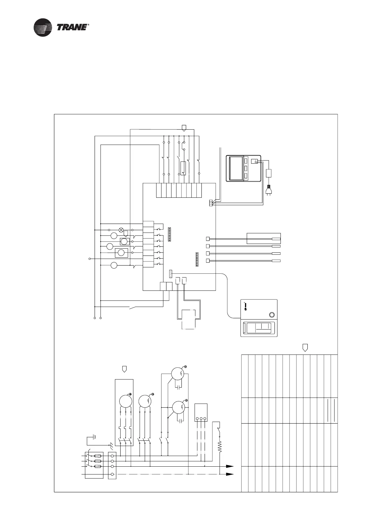
Wiring Diagram
The following wiring diagrams are only for reference, and the supplied wiring diagram Included in the
unit shall prevail.
CGAR/K0305R*/0505R*/0605R*
N
U
(Single compressor)
3
Transformer
RD
WH
water inlet sensor
water outlet sensor
Discharge sensor
Defrost sensor
AC 220V~
N
47811
Controller
12
16
RD
WH
YL
MC
MC
380V~/50Hz/3φ~N
N
C0MP
M
3~
CCH
N
V
RFS
C
A
B
(11)
(14)
L
RD
WH
MP
PUMP
M
3~
(L1)
R
(L2)
(L3)
S
T
1N
U
15
20
21
YL
OVP
NU
UVW
30
6
HF
FAN
M
1~
FAN
M
1~
RD
YL
BU
BU
BK
BK
1
#
2
#
ADC_OD_C02
25
Option
22
Only for heat pump
Heat pump only
HP1
LF
BU
BU
LF
F1
F2
HF
BA
+12VGND
CN1
ABG
CN1
CN2
CN6
R
SW1
SW2
CN4
TH2
TH1
TH3
TH4
HEAT
FAN
PUMP
4WV
A-HT
L
4MV
HF
OV-FAN
OV-PUMP
LP1
FLOW
OV-COMP
N-COM
EN-SAVE
OV-HEAT
N
AL
Alarm indicator
EG-SAVE
Wiring Diagram
TRANE P/N 690140500001
TB1
To controller
RFS
COMP
MC
AL_IN
AL_OUT
LP1
FLOW
MP
HP1
OVP
CGAR/K0605R*
CGAR/K0505R*
CGAR/K0305R*
Description
MP
MC
MF
CCH
COMP
AL-OUT/IN
FLOW
LP
4WV
Description
Pump Contactor
Compressor Contactor
Fan Contactor
Crankcase Heater
Compressor
Alarm Output/Input
Low pressure switch
Reversing Valve
Flow Switch
N-COM
Common Neutral Line
Factory wiring
On-site wiring
EN-SAVE
Energy Saving/2-Way
FAN
Fan Motor
Cfr
TB
HEAT
A-HT
Fan capacitance
Terminal Blocks
Water Circuit Based
Plate Heat Exchanger Heater
PUMP
Water Pump
OV-PUMP
Pump Overload
Control panel
(Indoor installation)
C/H
C/H
Outer Cool/Heat Pump Setting
Communication with other units
power supply of the main controller
Main controller
OV-COMP
Compressor Overload
HP
High pressure switch
Auxiliary electric heating
3
LF
PS1
PS
Medium-pressure switch
HF
Fan high speed
LF
Fan low speed
Name
(option)
Name
Electrical Heating Control
Valve Interlock
3
3
3
Technical requirement
1、For all fault inputs.the unit is normal when power on and gives an alarm when power off.
2、The flow switch is installed on site and connected between terminals U and 15.
3、Single unit the pump is optional,if customer provide pump,each unit can use digital output
7 to control it ,while remove the wire jumper between terminal U and 22,connection to the
pump protection signal.
4、If use 2-valve interlock,please dial SW2-7 to "ON".
5、Control panel and main controller are optional.
 Loading...