26
Mini / Multi-Split Programmable Controller
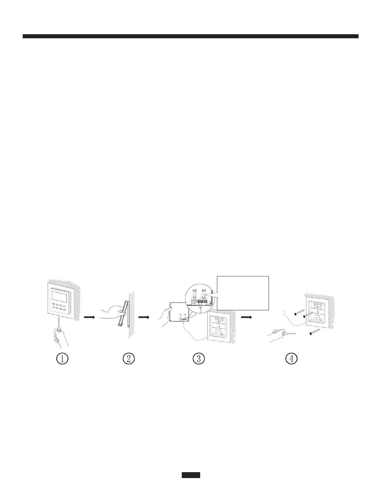
The specific installation steps are shown in Fig. 23:
Note: To ensure good communication, use the factory-provided communication wiring, or
equivalent. The recommended distance between the indoor unit and the controller is 25
feet (8m), but can be up to 65 feet (19.8m)
1. Check that the power is off before installing the wired controller to avoid the risk of
electric shock.
2. Pull out the communication line from the wall mounting hole, and pull this wire through
the hole at the rear side of the mounting plate of the wired controller.
3. Place the mounting plate of the wired controller on the wall and then use M4x25
screws, or similar, to fix the mounting plate onto the wall over the wiring access hole.
4. Connect the communication line to the port marked CN2 on the PCB (shown as H1 in
Figure 23) and make sure the line is tightly secured with no potential for a short circuit
to occur. Place the wiring into the groove at the left side of the wiring guide; secure the
front panel of the wired controller to the mounting plate.
Note:
• Keep the communication wire of the wired controller separated by at least 8 inches
from high voltage wiring, including wiring between the indoor and outdoor units.
• Do not run the wired controller wiring where it may be susceptible to electromagnetic
interference.
4.4 Disassembly
Fig. 24 Disassembly diagram for wired controller
Disconnect the
communication wire
from the larger H1
terminal (marked CN2
on the PCB).

 Loading...