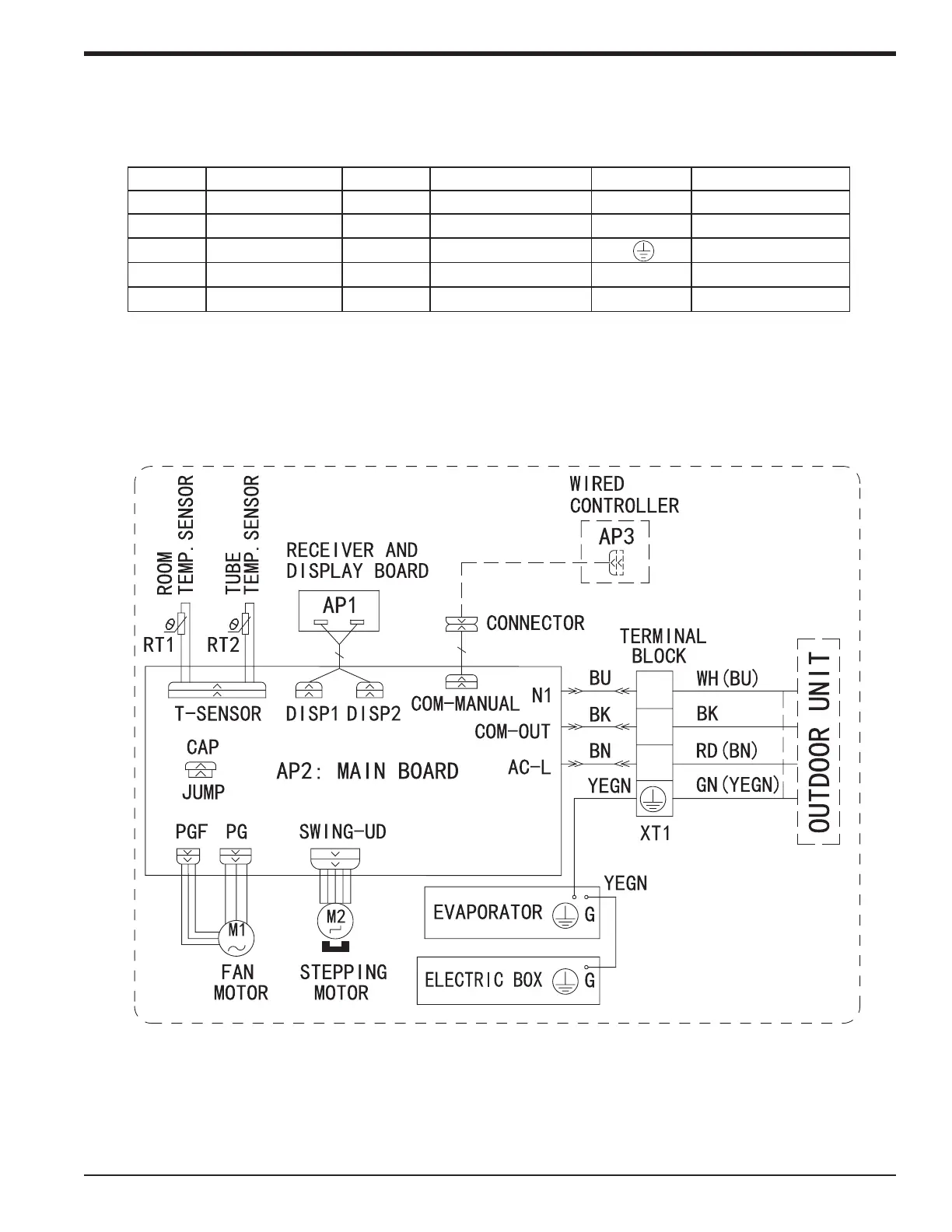
Wiring Diagrams
Indoor Unit
Color Key
Symbol Symbol Color Symbol Symbol Color Symbol Name
WH White GN Green CAP Jumper cap
YE Yellow BN Brown COMP Compressor
RD Red BU Blue Grounding wire
YE/GN Yellow/Green BK Black / /
VT Violet OG Orange / /
N(1)
2
3
Note: Jumper cap is used to determine fan speed and the swing angle of horizontal louver for this
model. The unit will not operate without the correct jumper cap. When replacing boards the jumper
cap must be moved to the new board.
NOTE: The wiring diagrams in this guide are included as a reference. The manufacturer
has a policy of continuous product and product data improvement and reserves the
right to change design and specications without notice. Always check the unit
nameplate and wiring diagram for the actual unit requirements.
88-M4MHW17-1A-EN 31
Installer's Guide
 Loading...