Run Test Mode
S8B1 - S8X1 - S8X2
Run Test Mode:
To enter Run Test Mode, scroll to using the Menu key, then push the op!on key. The LED will flash three
!mes, then begin the test.
To exit the test mode, momentarily push the Menu key, cycle power to the furnace, or make a valid thermostat
call for capacity or fan.
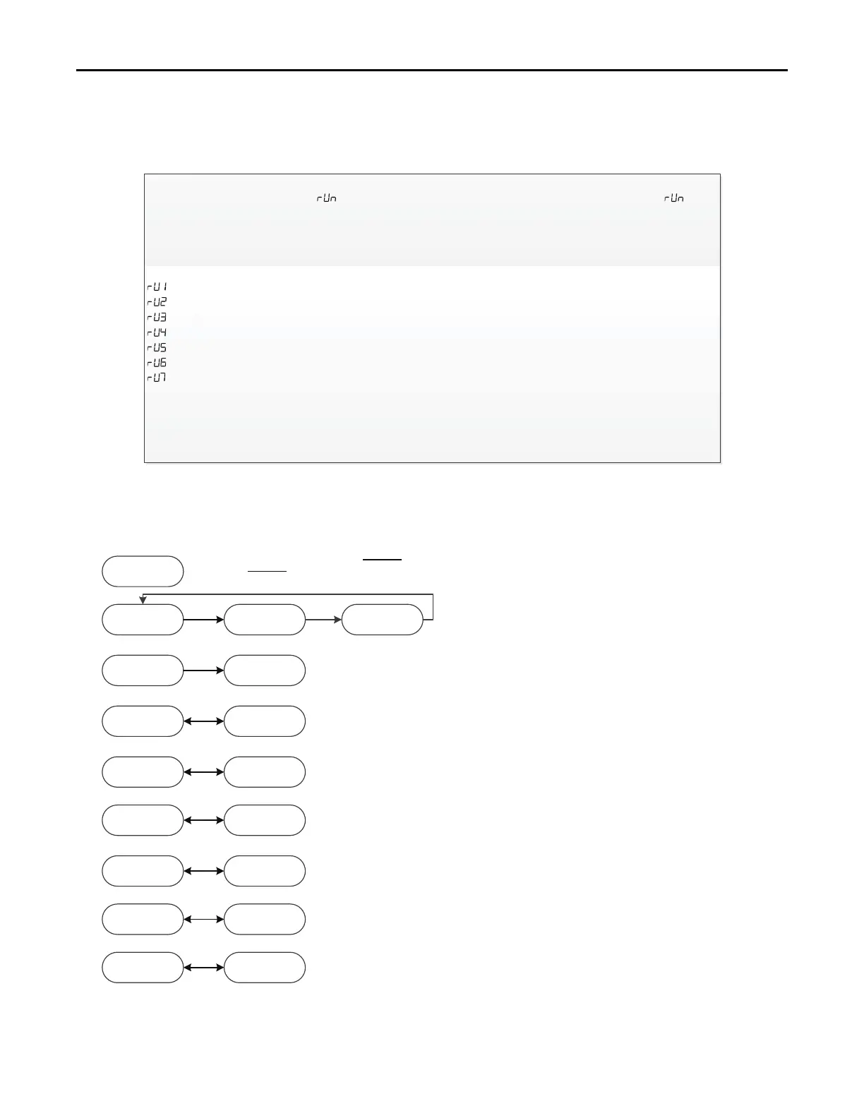
Sequence of Run Test Mode
-Turns the inducer on in 1
st
stage for 30 seconds
– Turns on the inducer on 2
nd
stage for 30 seconds (N/A for S8B1, S8X1)
– Turns the igniter on for 10 seconds
– Turns the circula!ng blower on 1 stage compressor speed for 10 seconds
– Turns the circula!ng blower on 2 stage compressor speed for 10 seconds (N/A for S8B1)
– Turns the circula!ng blower on 1
st
stage gas heat speed for 10 seconds
– Turns on the circula!ng blower on 2
nd
stage gas heat speed for 10 seconds (N/A for S8B1, S8X1)
The above sequence will repeat two more !mes unless the Run Test Mode is exited, see above.
Important: The Run Test Mode does not test fire the furnace or bring the outdoor unit on. It is designed to allow
the technician to observe each mode to ensure the IFC, inducer, and circula!ng blower are performing as
intended.
nd
st
Ht1 TP2
Ht2 Tp4
CL1 TP3
CL2 TP7
HP1 TP3
HP2 Tp7
COF Tp1
DFT TP3
S8B1 - S8X1 - S8X2
System Status Menu
Example
Tap #2
e3.1
Example
1st Stage Pressure
Switch Error
1dL
IdL = Idle, no demand for cooling, heating, or fan
Ht1 = Demand for 1st stage gas heat (HT = S8B1, S8X1)
Ht2 = Demand for 2nd gas heat
CL1 = Demand for 1st stage cooling (CP1 = S8B1, S8X1)
CL2 = Demand for 2nd stage cooling (CP2 = S8X1, N/A for S8B1)
HP1 = Demand for 1st stage heat pump (CP1 = S8B1, S8X1)
HP2 = Demand for 2nd stage heat pump (CP2 = S8X1, N/A for S8B1)
COf = Demand for continuous fan
dFt = Demand for outdoor unit defrost, furnace running in gas heat mode
tP1-9 = Tap selected for airflow
Note:
1. The menu status displayed is solely dependent on the input of
24VAC that is applied to the low voltage terminal strip.
2. The status will alternate between the system mode and the airflow
request every 2 seconds.
3. If an error occurs, an E*.* will alternately flash with the system
mode and airflow request. See first example.
 Loading...