18-CE16D1-1B-EN
55
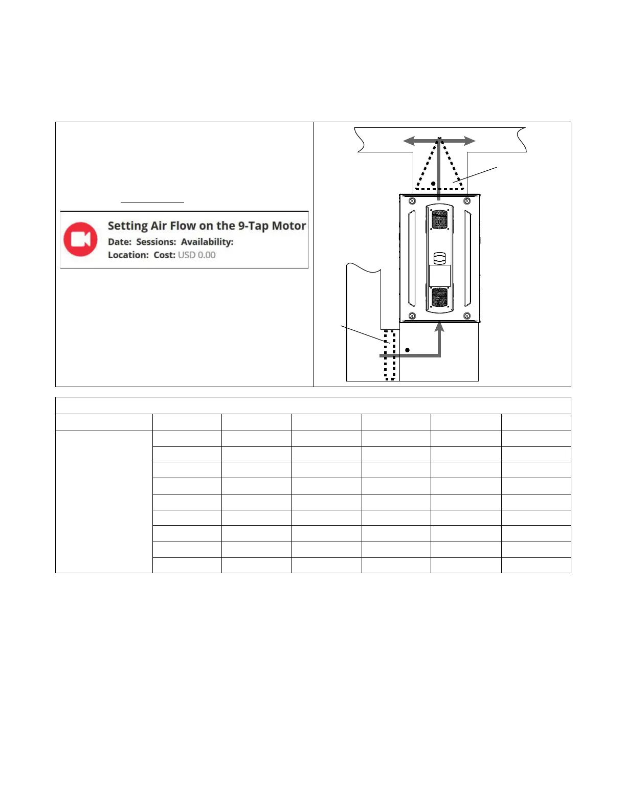
Setting Airflow
With all ductwork connected and a clean filter in place, measure the
External Static Pressure (ESP) of the unit in locations below. Use the
appropriate airflow table for the furnace and outdoor unit installed.
Note: Airflow tables are located in the Service Facts literature.
Measurements must be made prior to the evaporator coil, if equipped,
and after the filter.
Note: Check out fieldtechhelp.com to watch a short video.
Evaporato
r
Coil
Clean
Filter
Furnace Airflow (CFM) Vs. External Static Pressure (in. W.C.)
Model
Tap
0.1 0.3 0.5 0.7 0.9
S8B1B080M4PS
S8X1B080M4PS
S8X2B080M4PS
1 633 297 — — —
2 957 800 719 428 213
3 1220 1080 940 800 660
4 1403 1298 1192
1087
(a)
981
5 1524 1428 1336 1248 1164
6 1684 1574 1544 1401 1337
7 1700 1625 1551
1476
(b)
1401
(c)
8 1858 1790 1723 1656 1589
9 1967 1898 1829 1760 1691
This is an Example Airflow Table only. See Service Facts for complete Airflow data.
(a)
Exapmple 1, 2
(b)
Example 1
(c)
Example 2
Example 1: S8X2B080M4PS (Default Tap 7)
Cooling / HP
• 3 Ton Single Stage Outdoor
• Total ESP = 0.7” W.C.
• Required Airflow = 1050 cfm (3T x 350 cfm/ton)
• New Tap Number = Tap 4
Example 2: S8X2B080M4PS (Default Tap 3 & 7)
• 4 Ton Two Stage Outdoor
• Total 2
nd
Stage ESP = 0.9” W.C.
• Total 1
st
Stage ESP = 0.6” W.C.
• Required 2
nd
Stage Airflow = 1400 cfm (4T x 350
cfm/ton)
• Required 1
st
Stage Airflow = 1050 cfm (2
nd
stage
airflow x .75)
• New 2
nd
Stage Tap Number = Tap 7 (no change)
• New 1
st
Stage Tap Number = Tap 4
 Loading...