S8V2-SVX001-1A-EN
45
Table 16. Low Voltage Maximum Wire Length
The Low Voltage Maximum Wire Length table
defines the size and combined total maximum
length of the low voltage wiring from the
outdoor unit, to the indoor unit, and to the
thermostat.
Note: The use of color coded low voltage wire
is recommended to simplify
connections between the outdoor unit,
the control, and the indoor unit.
Control Wire — Communicating
WIRE SIZE MAX. WIRE LENGTH
18 AWG 500 FT. Combined
Control Wire — 24 Volt
WIRE SIZE MAX. WIRE LENGTH
18 AWG 100 FT. Combined
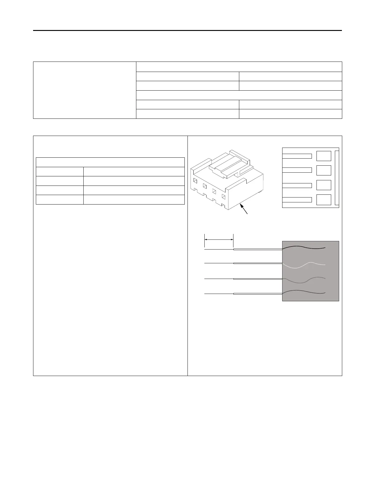
Table 17. Link Communicating Low Voltage Wire Connectors
Link mode uses simple connectors for low voltage connections. These
connections are color coded which makes the installation easier and
quicker.
Wire Colors
R Red
DH White
DL Green
B Blue
Do the following to make the connections from the actual thermostat
wire to the connector.
Note: These connectors are necessary at the communicating outdoor
unit, communicating indoor unit, distribution board(s), system
controller and communicating accessories.
1. Strip the Red, White, Green and Blue thermostat wires back 1/4”.
2. Insert the wires into the connector in the correctly colored
locations.
3. When you feel it release, allow each wire to slide in
further.
4. Pull back on the wires individually and slightly and check if the
wires are seated properly. If each wire does not pull out for all four
wires, the connection is complete.
5. Connectors are ONE TIME USE. If a 18 ga. Thermostat wire gets
broken off inside of the connector, the connector will need
replaced.
6. Wire colors are for illustration purposes only. If using a different
color, ensure it lands at the correct terminal throughout all of the
communicating control wiring.
Connect the CAN connector into the male coupling on the low voltage
harness at the Outdoor unit.
This furnace has three dedicated CAN connectors on the Integrated
Furnace Control (IFC). In Link communicating mode, all of them are in
the communicating loop. It does not matter which connector is used
for the Thermostat, System Controller (HUB), or Outdoor unit. Link
accessories can be connected to the Distribution Board if needed.
R DH DL B
CAN Connector
Strip the control
wire back- 1/4”
Note: For use with 18 ga. solid core thermostat wire.
FFuurrnnaaccee GGeenneerraall IInnssttaallllaattiioonn
 Loading...