44
S8V2-SVX001-1A-EN
1. SSeeccuurree tthhee sshheeaatthheedd wwiirriinngg ttoo tthhee IIFFCC uussiinngg tthhee
ffaaccttoorryy ssuupppplliieedd wwiirree ttiieess..
BAYSENSC360 - Optional Kit for
24V Mode
2. MMoouunntt SSuuppppllyy AAiirr TTeemmppeerraattuurree SSeennssoorr
The Supply Air Sensor (BAYSENSC360) must be mounted on the
leaving side of the cooling coil, or the maximum distance allowed by
the wire length on a furnace only application. Testing has shown the
left side of the plenum delivers the best average temperature. If the
left side cannot be used, take several readings to determine the best
place to mount the sensor for your application.
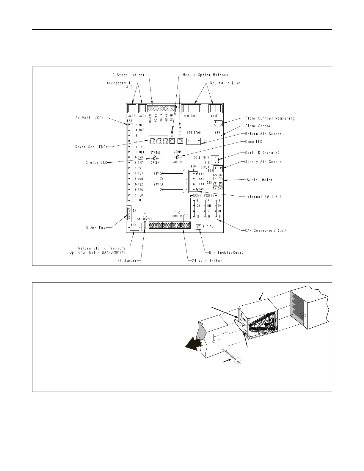
The Supply Air Sensor plugs into connector E22 of the IFC (See IFC
layout). In the Diagnostic App, this sensor is defaulted OFF and must
be configured to ON.
Note: Supply Air Temp Sensor (SAT) is used in Link Communicating
mode and is optional in 24 volt mode.
Note: Supply Air Temp Sensor (SAT) ships with SC360 System
Controller.
Note: Supply Air Sensor kit is BAYSENSC360.
Note: The return air sensor is located within the blower wiring
harness, behind the blower panel. In the Diagnostic App, this
sensor is defaulted ON.
AIRFLOW
FURNACE
DUCT
CASED COIL
SPLASH
GUARD
APEX OF COIL POINTS
AWAY FROM FURNACE
8” Min.
SUPPLY AIR
TEMPERATURE
SENSOR
FURNACE
FFuurrnnaaccee GGeenneerraall IInnssttaallllaattiioonn
 Loading...