48
S9V2-SVX001-1A-EN
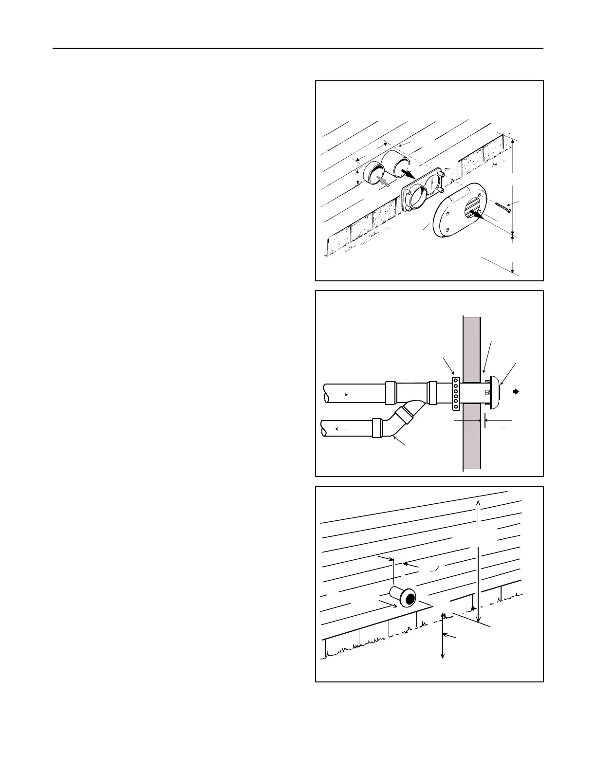
Horizontal Venting Through Wall with
Concentric Vent Kit
TThheessee FFuurrnnaacceess mmaayy bbee iinnssttaalllleedd aass ddiirreecctt vveenntt ((aass
sshhiippppeedd)) oorr aass nnoonnddiirreecctt vveenntt.. IInnssttaallllaattiioonn mmuusstt
ccoonnffoorrmm ttoo nnaattiioonnaall,, ssttaattee,, aanndd llooccaall ccooddeess..
The BAYVENT200B, BAYVENTCN200B,
BAYAIR30AVENTA, and BAYAIR30CNVENT vent & inlet
terminals kits must be located at least 12" minimum
above normally expected snow accumulation level.
Avoid areas where staining or condensate drippage
may be a problem.
Location of the vent/wind terminal should be chosen to
meet the requirements for either direct or non-direct
vent applications.
PPIITTCCHH —— Venting through the wall must maintain 1/4"
per foot pitched upward to insure that condensate
drains back to the Furnace.
FFLLUUEE GGAASS DDEEGGRRAADDAATTIIOONN —— The moisture content
of the flue gas may have a detrimental effect on some
building materials. This can be avoided by using the
roof or chimney venting option. When wall venting is
used on any surface that can be affected by moisture, it
is recommended that a corrosion resistant shield (24
inches square) be used behind the vent terminal. This
shield can be wood, plastic, sheet metal, etc. Also,
silicone caulk all cracks, seams and joints within 3 feet
of the vent terminal.
The vent for this appliance shall not terminate
1. Over public walkways; or
2. Near soffit vents or crawl space vents or other areas
where condensate or vapor could create a nuisance
or hazard or cause property damage; or
3. Where condensate vapor could cause damage or
could be detrimental to the operation of regulators,
relief valves. or other equipment.
For Canadian installations, if you used a ULC-S636
approved manufactured modular venting system, a
copy of the manufacturer's instructions should remain
with the system. The installation instruction can be
obtained from the vent termination manufacturer.
BAYVENTCN200B and BAYAIR30CNVENT meet ULC-
S636 requirements.
Figure 1. BAYVENT200B / BAYVENTCN200B
Note: For Canadian applications, horizontal vent termination
kits must meet ULC-S636.
VENT
COMBUSTION
AIR
VENT
VENT
PLATE
VENT
CAP
12" MINIMUM
TO OVERHANG
MAINTAIN 12" MINIMUM CLEARANCE
ABOVE HIGHEST ANTICIPATED SNOW LEVEL
OR GRADE WHICHEVER IS GREATER
SCREWS
(4 req.)
ANCHORS
(4 req.)
7.2"
3.2"
Figure 2. BAYAIR30AVENTA / BAYAIR30CNVENT(Sidewall)
RAIN CAP
COMBUSTION AIR
STRAP
(FIELD SUPPLIED)
COMBUSTION
AIR
VENT
ELBOW
(FIELD
SUPPLIED)
VENT
1" + 1/2"
COMBUSTION
AIR
12" MIN TO
OVERHANG
1" + "
VENT
1
2
MAINTAIN 12 IN.
MINIMUM CLEARANCE
ABOVE HIGHEST
ANTICIPATED SHOW
LEVEL OR GRADE
WHICH EVER IS GREATER
FFuurrnnaaccee GGeenneerraall IInnssttaallllaattiioonn
 Loading...


