CLEARING THE LAST 6 FAULTS:
To clear the stored faults, scroll to the last 6 faults
menu (L6F), enter the menu by scrolling to the right
and hold the “OPTION” key for at least 5 seconds.
Release and a set of 3 dashes will be seen 3 !mes.
This confirms the faults have been cleared.
SETTING UP YOUR SYSTEM:
To change any factory default value, first remove any “call”
from the furnace and allow any fan off delays to finish. (
should be seen on the display)
Scroll to the selected Menu item by momentarily depressing
the “MENU” key and then depress the “OPTION” key to the
desired se$ng. Then momentarily depress the “MENU” key
again to save the change.
CFM per Ton selec!ons range from 290 – 450
Important:
When applied with zoning or a VSPD outdoor unit,
the CFM/Ton must be set to 400
Gas Hea!ng CFM shown is 2
nd
stage airflow. 1
st
stage
airflow is ~80% of the selected 2
nd
stage airflow and
cannot be adjusted.
Gas hea!ng CFM can be adjusted while the unit is
opera!ng in gas heat mode to enable the technician to
quickly adjust to the manufacturer's suggested heat
rise across the heat exchanger.
Mulply the value shown by 10 for actual airflow.
Model Gas Heang CFM [ ]=Default
Upflow
S9V2B040U3PSBC 088 [088], 140, 065, 083
S9V2B060U4PS 116 [116], 130, 099, 109
S9V2B080U4PS 126 [126], 133, 146, 120
S9V2C080U5PSBC 145 [145], 156, 208, 119
S9V2C100U5PS 206 [206], 215, 159, 198
S9V2D120U5PS 195 [195], 225, 156, 185
Downflow
S9V2B040D3PS 088 [088], 095, 125, 065
S9V2B060D3PS 103 [103], 113, 135, 090
S9V2B080D4PS 133[133], 148, 120, 126
S9V2C100D5PS 187[187], 210, 152, 180
S9V2D120D5PS 225[225], 175, 185, 195
Model ODT Opons [ ]= Default
Upflow
S9V2B040U3PS 3T[3T], 1.5T, 2T, 2.5T
S9V2B060U4PS 4T[4T], 1.5T, 2T, 2.5T, 3T, 3.5T
S9V2B080U4PS 4T[4T], 2T, 2.5T, 3T, 3.5T
S9V2C080U5PS 5T[5T], 3T, 3.5T, 4T, 4.5T
S9V2C100U5PS 5T[5T], 2.5T, 3T, 3.5T, 4T, 4.5T
S9V2D120U5PS 5T[5T], 3T, 3.5T, 4T, 4.5T
Downflow
S9V2B040D3PS 3T[3T], 1.5T, 2T, 2.5T
S9V2B060D3PS 3T[3T], 1.5T, 2T, 2.5T
S9V2B080D4PS 4T[4T], 2T, 2.5T, 3T, 3.5T
S9V2C100D5PS 5T[5T], 2.5T, 3T, 3.5T, 4T, 4.5T
S9V2D120D5PS 5T[5T], 3T, 3.5T, 4T, 4.5T
Note:
Do not adjust COF above 50%.
S9V2B040U3PSBD 088 [088], 120, 065, 083
S9V2C080U5PSBD 145 [145], 156, 170, 119
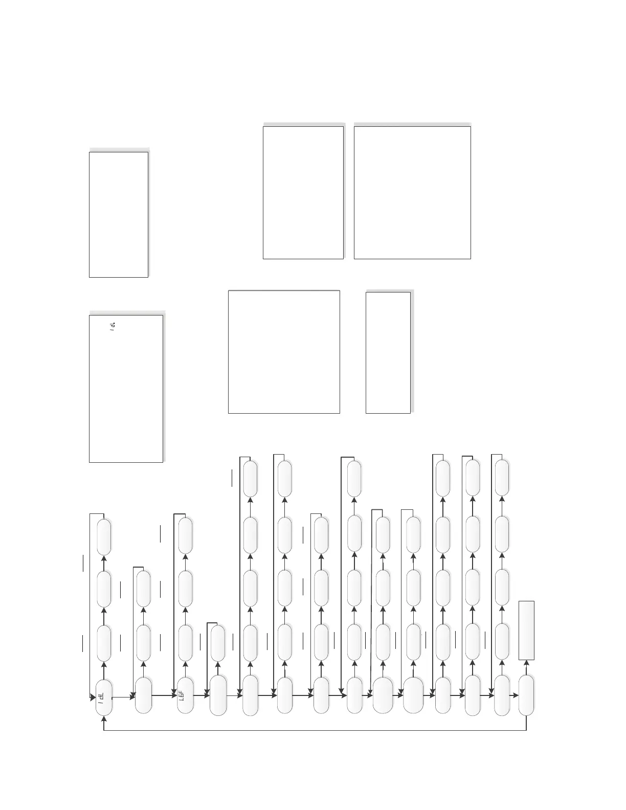
IdL
Status Menu
Err
Ac!ve Errors
Ht1 Arf
Example
1
st
stage Gas Heat
Example
800 CFM
E3.4
Example
2
nd
Stage Pressure
Switch Error
E3.1
Example
1st Stage Pressure
Switch Error
L6F
Last 6 Faults
E3.4 E3.1 E04
Example
2
nd
Stage Pressure
Switch Error
Example
1st Stage Pressure
Switch Error
Example
Open Limit Switch
Error
CR
Control Release#
021
Example
So+ware Version #
COd
Cooling Off Delay
000 090 180 EH
Example
seconds
Example
Enhanced Mode
ODT
OD Tonnage
3.0
Example
Outdoor Nominal Tonnage
1.5 2.0 2.5
ODU
OD Unit Type
1-1 2-1
Example
COF
Con!nuous Fan
50 75
Example
50% Cooling Airflow
CPC
Cooling CFM
per Ton
350 370
400
Example
CFM per Ton
100 140
180 60
HOD
Heat Off Delay
Example
Seconds
600 900
000 300
ISD
Inter-Stage Delay
Example
Seconds
116 130
099 109
G
HC
Gas Hea!ng CFM
Example
2
nd
stage Hea!ng CFM
S9V2-PS
Control System Menu
2-2
Example
2 stage 1 compressor
Example
2 stage 2 compressor
080
CPH
Hea!ng CFM
per Ton
350 370
400
Example
CFM per Ton
rUn
Run Test Mode
See Run Test Menu
100
25
1 stage 1 compressor
 Loading...


