22
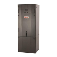
STEP 1 - Remove Heater, Coil, and Line Set panels.
(See Section 2.2 Panel Removal)
Section 11. Refrigerant Line Brazing
11.1 Braze The Refrigerant Lines
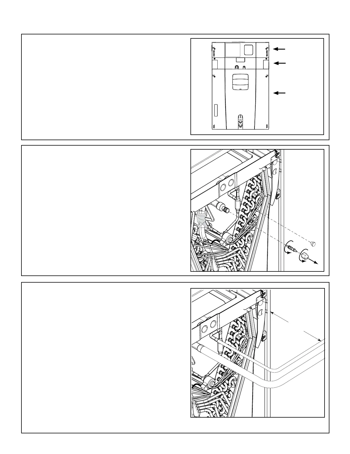
STEP 6 - Connect, but do not braze, field line set to
indoor coil.
Allow a minimum of three (3) inches of refrigerant
line set before using an elbow coupling.
Important: Service access to the auxiliary heater
must remain unobstructed.
Important: Do NOT unseal coil refrigerant connec-
tion stubs until ready to make connections.
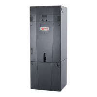
STEP 2 - Remove the plastic cap and Schrader valve
core from the gas line.
STEP 3 - Wrap the vapor sensor with a wet rag.
Important: Care must be taken during solder cap
removal and brazing to avoid damage to unit compo-
nents and wiring.
STEP 4 - Apply low heat to the solder cap to slowly
heat the solder. (Do not apply direct heat to the va-
por line) Use adjustable pliers to grab the flare fitting
and remove the solder cap.
STEP 5 - Remove the sealing plug from the indoor
coil liquid connection.
Heater
Panel
Line Set
Panel
Coil
Panel
3” MIN
1
2
3

 Loading...