40
Section 17. Start Up
17.1 System Charge Adjustments
Section 16. Filters
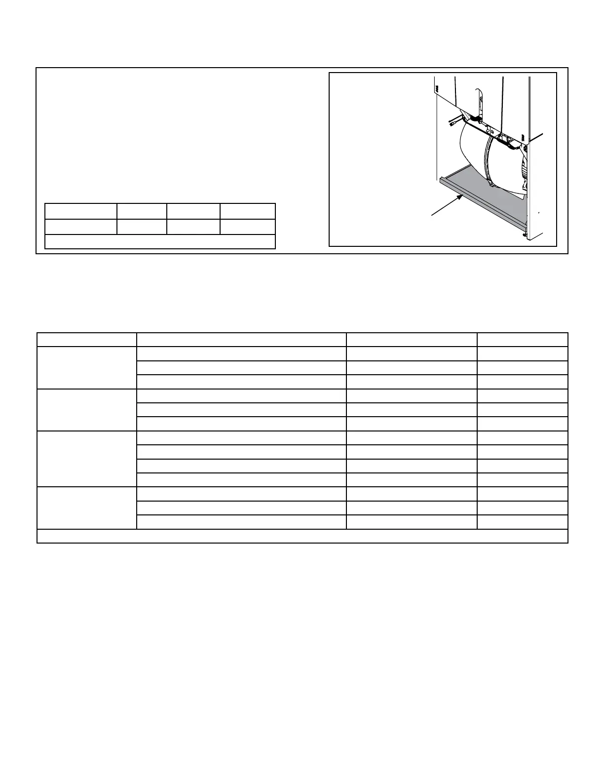
16.1 Filter Considerations
Filter in
air handler
cabinet
(Upflow
Application)
• A filter must be installed within the system.
• A filter channel is provided in the unit, at the bot-
tom of the Blower/Filter compartment.
• For customer ease of fil ter maintenance, it is
recommended that a properly sized remote filter
grill(s) be installed for units that are difficult to
access. Airflow should not exceed the maximum
rated velocity of the filter being used.
Cabinet Size* A B C
Filter Size 16 x 20 20 x 20 22 x 20
* Cabinet size is indicated by the 7th digit in model number.
Table 16.1 Filter Sizes
Sytem Matched with: Indoor Unit Model No. Outdoor Unit Model No. Subcooling
16 SEER HP TAM7A0B30H21SB 4A6H6024E/G, 4TWX6024E/G 9°
TAM7A0C36H31SB 4A6H6036E/G, 4TWX6036E/G 10°
TAM7A0C48H41SB 4A6H6048E/G, 4TWX6048E/G 8°
16 SEER AC TAM7A0B30H21SB 4A7A6024E/G, 4TTX6024E/G 8°
TAM7A0C36H31SB 4A7A6036E/G, 4TTX6036E/G 8°
TAM7A0C48H41SB 4A7A6048E/G, 4TTX6048E/G 8°
20 SEER HP TAM7A0B30H21SB 4TWZ0024A, 4A6Z0024A 9°
TAM7A0C36H31SB 4TWZ0036A/B, 4A6Z0036A/B 10°
TAM7A0C48H41SB 4TWZ0048A/B, 4A6Z0048A/B 12°
TAM7A0C60H51SB, TAM7B0C60H51SA 4TWZ0060A, 4A6Z0060A 12 °
20 SEER AC TAM7A0B30H21SB 4TTZ0024A, 4A7Z0024A 9°
TAM7A0C36H31SB 4TTZ0036A/B, 4A7Z0036A/B 11°
TAM7A0C48H41SB 4TTZ0048A/B, 4A7Z0048A/B 13°
All other matches must be charged per the nameplate charging instructions.

 Loading...