Installation
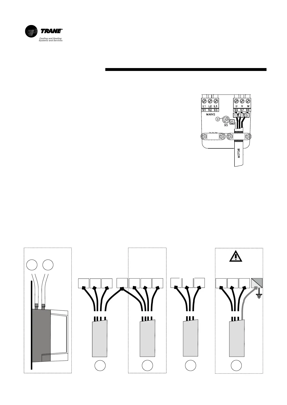
Exhaust / Return fan cable
connection
Run the power exhaust fan motor power
cables to the speed inverter.
Connect the three phases and ground
cable(s) to the MOTOR terminal of the
speed inverter.
Respect the cable numbers as shown in
Figure 7.
If two exhaust fan motors are installed,
repeat the operation two times.
The cable shield must be connected to the
chassis by means of the cable clamp.
M
56 57 58
1 2 3
400V / 3 /50Hz
B
50 51 52
1 2 3
24VAC
ON/OFF
50 51 55
5 1 2 3
24VAC
0-10VDC
P+ P-
B57
+ -
R’
0V
+24VAC
0-10VDC
input
0V
+24VAC
24VAC
input
L1 L2 L3
Feedback
R
50 51 53
54
1 2 3 5
24VAC
0-10VDC
0V
+24VAC
0-10VDC
input
Only PHE
125-155-175-200-250-265-290-340
Only PHE
Only ERW
WARNING!: insulate the cables to ensure there has not been any cable damage during shipping and installation.
Figure 7 -
Connect to the spring terminal blocks X50-
X51-X52-X53-X56-X57-X58. Connect
cables according to the following wiring
diagrams.
For Plate Heat exchanger versions, connect
the plastic hose to the differential defrost
pressure switch port.
Figure 8 - Connections
 Loading...