RLC-SVU007E-GB
11
11UNT-PRC002-GB
Sound power levels
Discharge
Measurement conditions:
Measurements taken in a room adjacent to the room containing the FWD, at the outlet of the rectangular duct (1.5 m
long) fixed to its discharge opening.
Fan Power level in dB(A), per Hz frequency band Overall power
Unit speed 125 250 500 1000 2000 4000 8000 dB(A)
1 55 50 42 37 37 31 30 46
FWD 08 2 57 54 47 40 30 38 40 50
3 58 57 50 42 32 40 43 53
1 57 51 45 42 34 33 28 48
FWD 10 2 58 54 48 45 38 39 35 51
3 60 58 50 48 40 42 39 54
1 57 51 45 42 34 33 28 48
FWD 12 2 58 54 48 45 38 39 35 51
3 60 58 50 48 40 42 39 54
1 56 62 50 48 39 38 36 56
FWD 14 2 61 66 55 53 47 46 45 60
3 63 69 58 56 50 50 49 63
1 57 63 51 49 40 39 37 57
FWD 20 2 61 66 55 53 47 46 45 60
3 63 69 58 56 50 50 49 63
Intake
Measurement conditions:
Measurements taken at the horizontal air intake.
Fan Power level in dB(A), per Hz frequency band Overall power
Unit speed 125 250 500 1000 2000 4000 8000 dB(A)
1 56 55 55 53 46 45 42 57
FWD 08 2 63 62 60 60 53 53 53 64
3 66 65 63 62 56 55 57 67
1 62 58 55 58 51 48 44 61
FWD 10 2 66 63 60 62 56 55 52 66
3 70 67 63 65 59 59 57 69
1 62 58 55 58 51 48 44 61
FWD 12 2 66 63 60 62 56 55 52 66
3 70 67 63 65 59 59 57 69
1 66 65 65 65 57 50 46 68
FWD 14 2 73 72 69 71 64 59 57 74
3 78 76 73 75 69 64 63 78
1 68 72 64 64 56 52 50 69
FWD 20 2 76 76 68 71 65 61 61 75
3 78 79 71 74 69 66 66 78
External setpoints & capacity outputs (Optional)
External Chilled Water Setpoint (ECWS)
The UC800 provides inputs that accept either 4-20 mA or 2-10 VDC signals to set the external chilled water setpoint
(ECWS). This is not a reset function. The input defines the setpoint. This input is primarily used with generic BAS
(building automation systems).
Functional Description
When the unit is in cooling mode, the external water setpoint (EWS) will correspond to the chilled water setpoint.
The external chilled water setpoint shall have a configurable minimum and maximum.
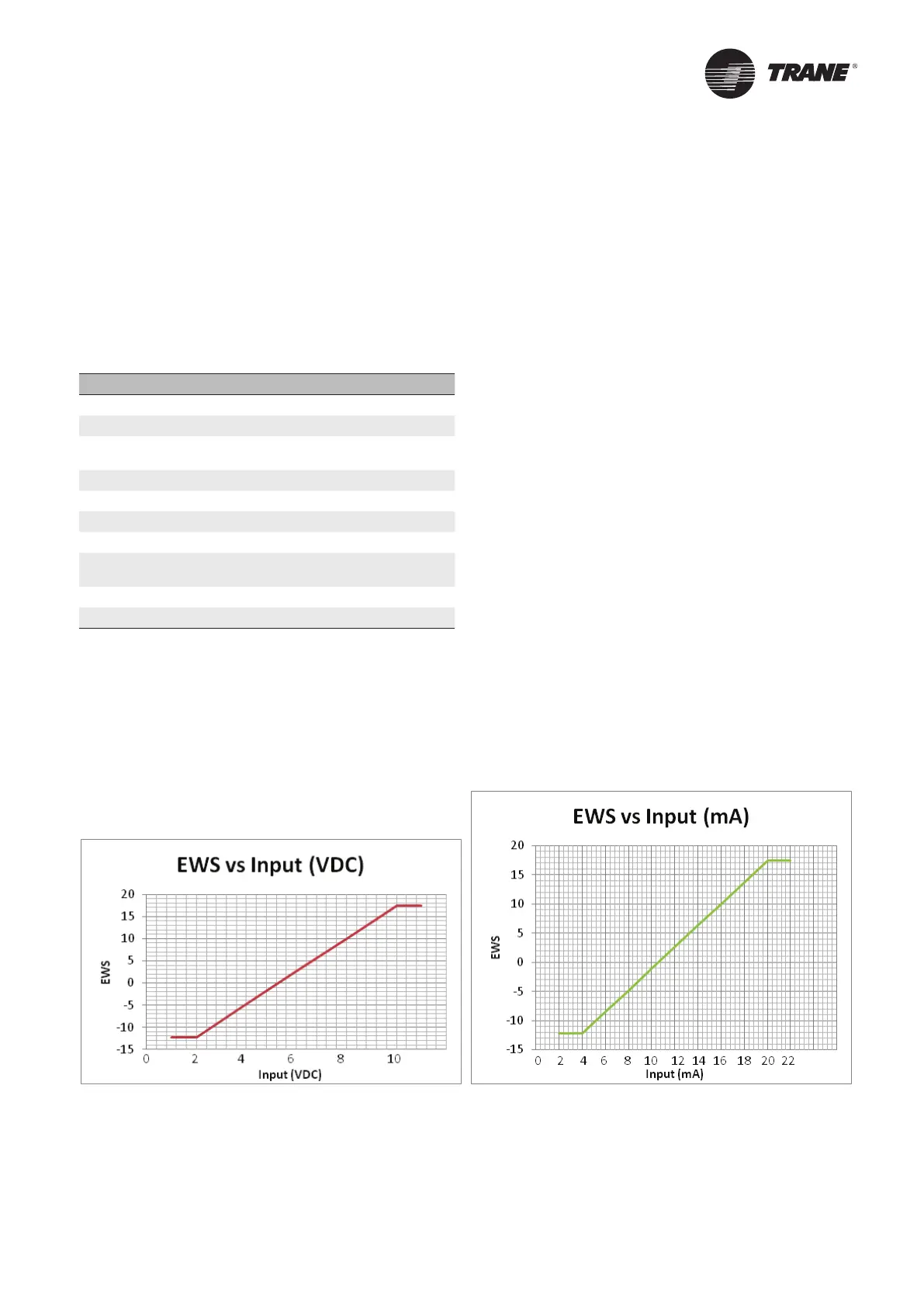
2-10 VDC and 4-20 mA shall each correspond to an EWS range with a configurable minimum and maximum EWS.
The following relationships exist:
Input Signal External Water Setpoint
< 1 VDC Invalid
1 VDC to 2 VDC min
2 VDC to 10 VDC
min + (max – min) *
(Signal – 2) / 8
10 VDC to 11 VDC max
> 11 VDC Invalid
< 2 mA Invalid
2 mA to 4 mA min
4 mA to 20 mA
min + (max – min) *
(Signal – 4) / 16
20 mA to 22 mA max
> 22 mA Invalid
If the ECWS input develops an open or short, the LLID will report either a very high or very low value back to the
main processor. This will generate an informational diagnostic and the unit will default to using the Front Panel (TD7)
Chilled Water Setpoint.
Tracer TU Service Tool is used to set the input signal type from the factory default of 2-10 VDC to that of 4-20 mA.
Tracer TU is also used to install or remove, enable or disable the External Chilled Water Setpoint.
Examples
The following graphs are examples for min = -12.2°C and max = 18.3°C:

 Loading...


