18 18-CD31D1-3
Installer’s Guide
FIRE OR EXPLOSION HAZARD
Failure to follow the safety warnings exactly could result
in serious injury, death or property damage.
Never test for gas leaks with an open flame. Use a com-
mercially available soap solution made specifically for
the detection of leaks to check all connections. A fire or
explosion may result causing property damage, personal
injury, or loss of life.
GAS PIPING
FIRE - EXPLOSION HAZARD
DO NOT RUN FLEXIBLE GAS LINE THROUGH THE FUR-
NACE CABINET WALL. FAILURE TO FOLLOW THIS WARN-
ING COULD RESULT IN PROPERTY DAMAGE, SERIOUS
PERSONAL INJURY, OR DEATH.
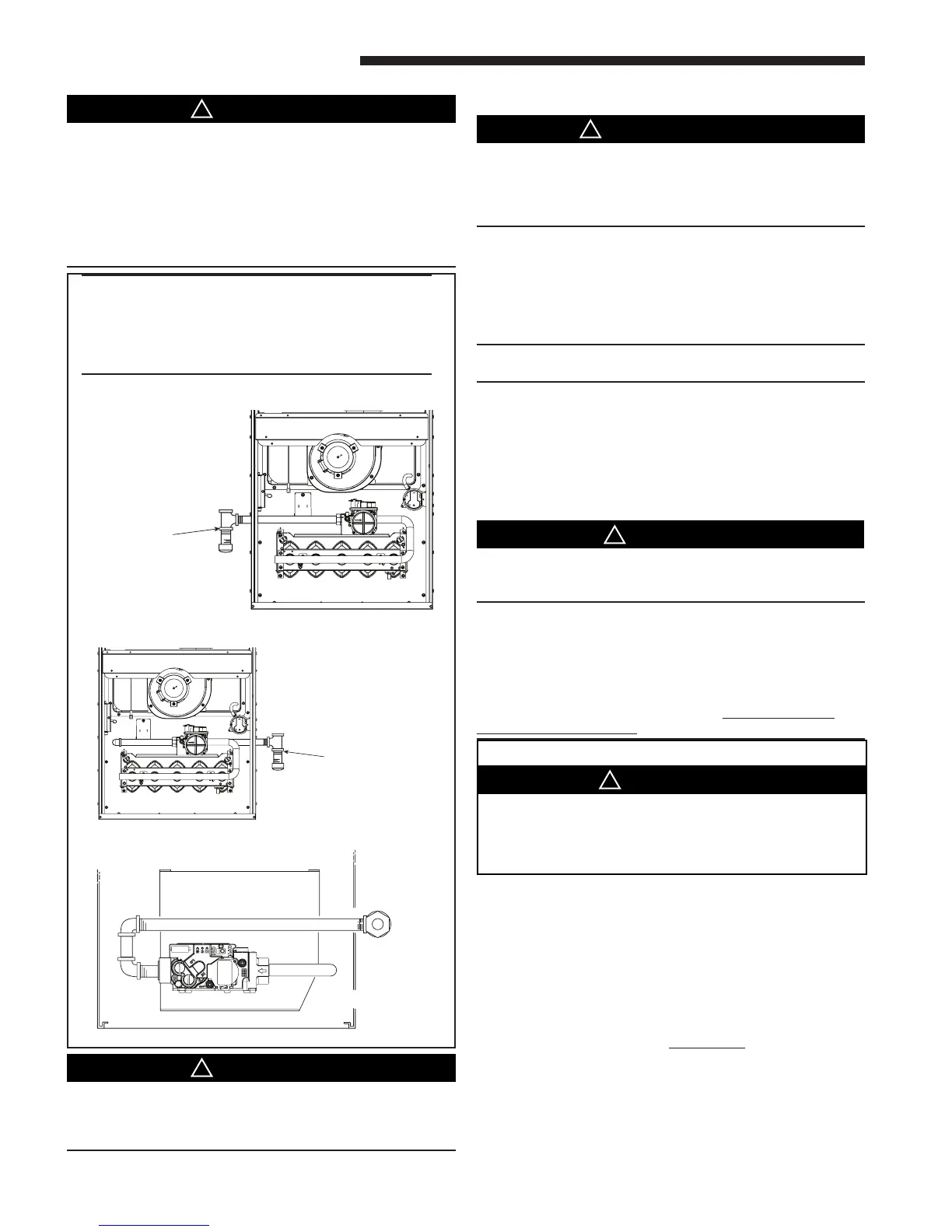
This unit is shipped standard for left side installation of
gas piping. A piping knockout is also provided in the right
side for an alternate piping arrangement. The installation
of piping shall be in accordance with piping codes and the
regulations of the local gas company. Pipe joint compound
must be resistant to the chemical reaction with liquefied pe-
troleum gases. Refer to piping Table 10 for delivery sizes.
NOTE: Refer to local codes and the National Fuel Gas
Code, current edition, for gas pipe requirements.
The furnace and its individual shut-off valve must be
disconnected from the gas supply piping system during any
pressure testing of that system at test pressures in excess
of 1/2 psig.
The furnace must be isolated from the gas supply piping
by closing its individual manual shut-off valve during any
pressure testing of the gas supply piping system at test
pressures equal to or less than 1/2 psig.
Use a backup wrench on the gas valve when installing gas
piping to prevent damage to the gas valve and manifold
assembly.
NOTE:
Maximum pressure to the gas valve for natural gas is
13.8" W.C. Minimum pressure is 5.0" W.C. Maximum pres-
sure to the gas valve for propane is 13.8" W.C. Minimum
pressure is 11.0" W.C.
All gas fittings must be checked for leaks using a soapy
solution before lighting the furnace. DO NOT CHECK
WITH AN OPEN FLAME!
The following warning complies with State of California law, Proposition 65.
Hazardous Gases!
Exposure to fuel substances or by-products of incomplete
fuel combustion is believed by the state of California to
cause cancer, birth defects, or other reproductive harm.
S
WARNING
!
COMBUSTION AND INPUT CHECK
1. Make sure all gas appliances are off except the furnace.
2. Clock the gas meter with the furnace operating (deter-
mine the dial rating of the meter) for one revolution.
3. Match the “Sec” column in the gas flow (in cfh) Table 13
with the time clocked.
4. Read the “Flow” column opposite the number of sec-
onds clocked.
5. Use the following factors if necessary:
For 1 Cu. Ft. Dial Gas Flow CFH =
Chart Flow Reading ÷ 2
For 1/2 Cu Ft. Dial Gas Flow CFH =
Chart Flow Reading ÷ 4
For 5 Cu. Ft. Dial Gas Flow CFH =
10X Chart Flow Reading ÷ 4
TO PREVENT AN EXPLOSION OR POSSIBLE INJURY,
DEATH AND EQUIPMENT DAMAGE, DO NOT STORE COM-
BUSTIBLE MATERIALS, GASOLINE OR OTHER FLAM-
MABLE VAPORS OR LIQUIDS NEAR THE UNIT.
TOP VIEW
AUTOMATIC GAS VALVE
WITH MANUAL SHUTOFF
LEFT SIDE PIPING (STANDARD)
TOP VIEW OF RIGHT SIDE PIPING
RIGHT SIDE PIPING (OPTIONAL)
H
IMPORTANT:
A sediment trap must be installed in the gas line
before the furnace gas valve. The sediment trap
must be located as close to the furnace cabinet
as practical.
 Loading...