16 18-CD33D1-4
Installer’s Guide
NOTE:
Follow venting instructions carefully when using PVC
cement.
IMPORTANT:
All joints must be water tight. Flue condensate is somewhat
acidic, and leaks can cause equipment damage.
Connection of the pipe and collar of the combustion air
inlet should just be a friction fit. It is recommended that
the inlet air joint be sealed with RTV type sealant to allow
the joint to be separated for possible future service. The
inlet and vent pipes must be properly supported through-
out the entire length.
Connection of the vent pipe to the vent collar should also
be accomplished using RTV type sealant. This type seal-
ant provides a connection which remains flexible and can
be separated in the future if service needs require the re-
moval of the vent pipe for service or clearance.
NOTE:
To ensure proper operation at the vent lengths indicat-
ed, the combustion air inlet and vent terminals should
be in the same pressure zone. Terminating the vent and
inlet in different pressure zones will change the maxi-
mum vent lengths and may cause nuisance tripping of
the pressure switch(es). The amount of change can not
be predicted. The selection of the inlet and outlet termi-
nal locations are the responsibility of the designer/in-
staller. If the installer chooses separate pressure zones
for the terminals, the combustion air inlet termination
must be in the higher (more positive) pressure zone.
HORIZONTAL VENTING
NOTE:
Vent termination kit BAYAIR30AVENTA or BAY-
VENT200B may be used in addition to the horizontal
and vertical termination options shown in Figure 26.
See Figure 31.
For Canadian applications ONLY: IPEX 196006 may
be used for horizontal and vertical terminations. IPEX
081216, IPEX 081218, and IPEX 081219 may only be
used for horizontal vent terminations.
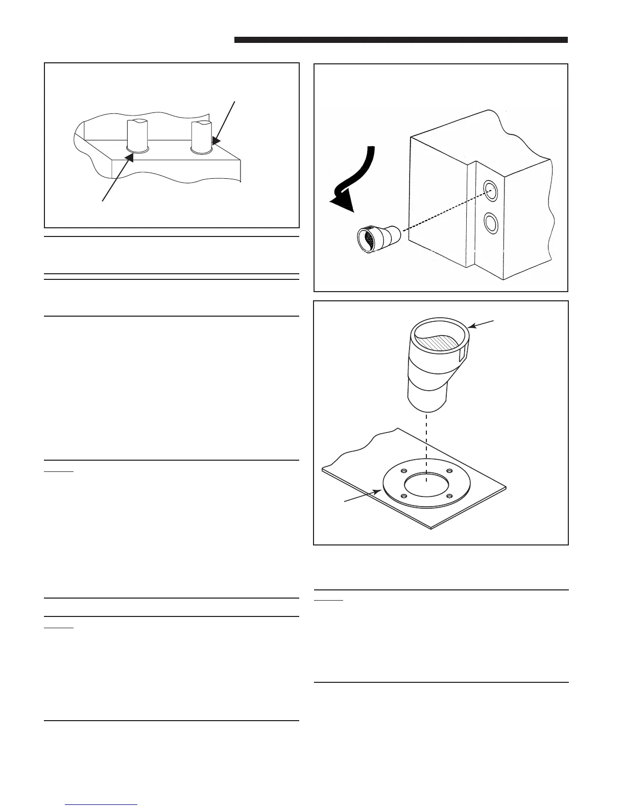
p
Seal VENT PIPE
with RTV sealant
Seal INLET AIR PIPE
with RTV sealant
Front of Furnace
VENT AND INLET AIR CONNECTIONS
LABEL
SAYS
"TOP"
STRAIGHT SIDE MUST BE
ON BOTTOM FOR PROPER
CONDENSATE DRAINAGE.
WHEN THE FACTORY SUPPLIED "OFF-SET" (2X3
REDUCING COUPLING) IS USED FOR 3" VENT PIPE
INSTALLATION, MAKE SURE THE MARKING "TOP" IS
LOCATED ON THE TOP SIDE OF THE PIPE.
a
s
2" TO 3" COUPLING
FURNACE
VENT
OUTLET
FACTORY SUPPLIED ONLY
WITH THE FOLLOWING
MODELS: *UH1C100A9H41B,
*UH1D120A9H51B, AND ALL
*DH1 DOWNFLOW MODELS
#CPL00938
HORIZONTAL INSTALLATION
Upflow/ Horizontal
NOTE:
In horizontal venting when the factory supplied “off-
set” (2X3 reducing coupling) is used for 3” vent pipe
installation, make sure the marking “Top” is located on
the top side of the pipe. The straight side must be on
bottom for proper condensate drainage. This coupling
is only factory supplied with *UH1C100A9H41B, *UH-
1D120A9H51B, and all downflow models.
 Loading...