28 18-CD29D1-11
Installer’s Guide
NOTE:
Use 1/2" or larger PVC or CPVC pipe and fittings as re-
quired for drain connections (fittings, pipe and solvent ce-
ment not provided).
NOTE:
A corrosion resistant condensate pump must be used if a
pump is required for a specific drain system.
IMPORTANT:
The condensate drain should be installed with provisions
to prevent winter freeze-up of the condensate drain line.
Frozen condensate will block drains, resulting in fur nace
shutdown. If the drain line cannot be installed in a condi-
tioned space, then UL listed heat tape should be applied
as required to prevent freezing (per manufacturer’s in-
structions). The heat tape should be rated at 5 or 6 watts
per foot at 120 volts. Self-regulating (preferred) or thermo-
statically controlled heat tape is required.
Evaporator and furnace condensate drain piping may be
manifolded together as shown in Figure 51. A primary
drain vent stack must be installed and terminated below
the outlet of the secondary heat exchanger drain connection
SEE
NOTE 6
From drawing B341437 Rv 1
FURNACE
TWIN
SEE
NOTE 7
B/C
B/C
TO 115 V 1 PH.,
60 HZ., POWER
SUPPLY PER
LOCAL CODES
HUM SEE
NOTE 5
EAC SEE
NOTE 5
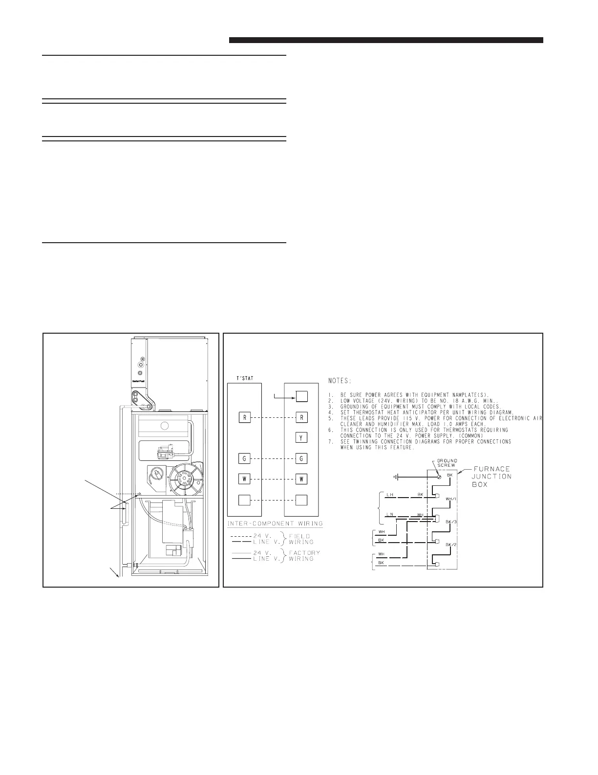
FIELD WIRING DIAGRAM FOR 1 STAGE FURNACE
1 STAGE HEATING
USING A 1 STAGE HEATING THERMOSTAT
NO COOLING
Primary drain vent
stack must terminate
below secondary heat
exchanger condensate
drain outlet.
To drain opening
If upflow furnace is
installed over a finished
ceiling, overflow from
the primary drain vent
stack must flow into an
auxillary drain pan to
prevent damage to the
finished ceiling below.
Q
to prevent water from damaging furnace controls if the pri-
mary drain outlet plugs up. Where the furnace is installed
above a finished ceiling, the primary drain vent stack must
be installed such that overflow from the vent stack opening
will flow into an auxiliary drain pan in order to prevent wa-
ter damage to the finished ceiling below.
TWINNING FURNACES
These furnaces may be twinned. Twinning requires that
two furnaces with the same configuration, capacity, and air-
flow must be used. They shall have common returns with
equal pressure drops or ducts with equivalent lengths and
sizes. See Field Wiring Diagrams for proper hookup.
 Loading...