32 18-CD29D1-11
Installer’s Guide
TABLE 15
4. Read the “Flow” column opposite the number of sec-
onds clocked.
5. Use the following factors if necessary:
For 1 Cu. Ft. Dial Gas Flow CFH =
Chart Flow Reading ÷2
For 1/2 Cu Ft. Dial Gas Flow CFH =
Chart Flow Reading ÷4
For 5 Cu. Ft. Dial Gas Flow CFH =
10X Chart Flow Reading ÷4
6. Multiply the final figure by the heating value of the
gas obtained from the utility company and compare
to the nameplate rating. This must not exceed the
nameplate rating.
Gas Valve Adjustment
Changes can be made by adjusting the manifold pressure
(See Table 17, or changing orifices (orifice change
may not always be required). To adjust the manifold
pressure:
1. Turn off all electrical power to the system.
2. Attach a manifold pressure gauge with flexible tub-
ing to the outlet pressure boss marked “OUT P” on
White-Rodgers gas valve model 36G or 36J. See Fig-
ure 58 for White-Rodgers gas valve model 36J. See
Figure 57 for White-Rodgers gas valve model 36G.
3. Loosen (Do Not remove) the pressure tap test set
screw one turn with 3/32" hex wrench.
a. The pressure tap adjustment kit (KIT07611) con-
tains a 3/32" hex wrench, a 5/16" hose and a con-
nector and can be ordered through Global Parts.
4. Turn on system power and energize valve.
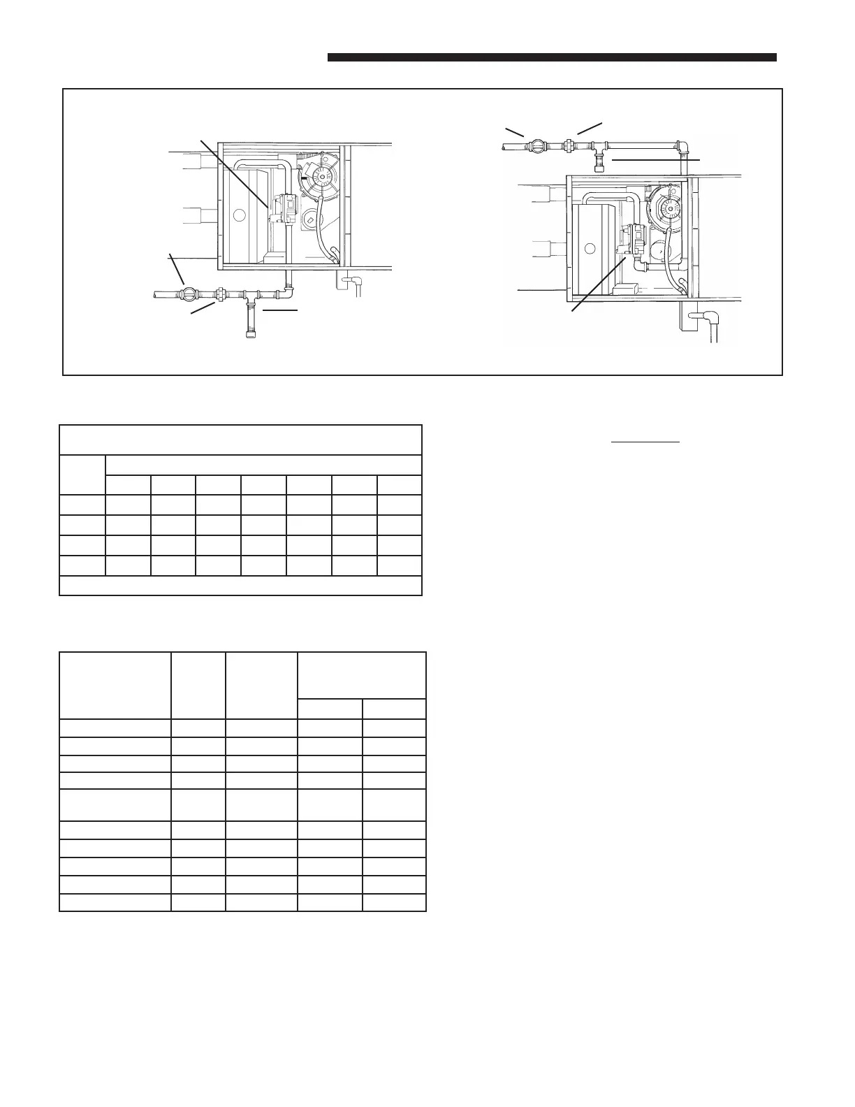
HORIZONTAL FURNACE GAS PIPING MAY BE FROM EITHER SIDE (UPFLOW SHOWN)
GROUND UNION JOINT
DRIP
LEG
AUTOMATIC GAS VALVE WITH
MANUAL SHUTOFF
MAIN MANUAL
SHUTOFF VALVE
GROUND
UNION JOINT
DRIP
LEG
MAIN MANUAL
SHUTOFF VALVE
AUTOMATIC GAS VALVE
WITH MANUAL SHUTOFF
R
ORIFICE SIZES
MODEL
INPUT
RATING
BTUH
NUMBER
OF
BURNERS
MAIN BURNER
ORIFICE
DRILL SIZE
NAT. GAS LP GAS
*UH1B040A9241A 40,000 2 45 56
*UH1B060A9361A 60,000 3 45 56
*UH1B080A9421B 77,000 4 45 56
*UH1C080A9601A 80,000 4 45 56
*UH1C100A9481A
*UH1D100A9601A
100,000 5 45 56
*UH1D120A9601A 110,000 6 45 56
*DH1B040A9241A 40,000 2 45 56
*DH1B065A9421A 60,000 4 48 56
*DH1C085A9481A 80,000 5 48 56
*DH1D110A9601A 110,000 6 48 56
NATURAL GAS ONLY
TABLE OF CUBIC FEET PER HOUR OF GAS
FOR VARIOUS PIPE SIZES AND LENGTHS
PIPE
SIZE
LENGTH OF PIPE
10 20 30 40 50 60 70
1/2 132 92 73 63 56 50 46
3/4 278 190 152 130 115 105 96
1 520 350 285 245 215 195 180
1-1/4 1050 730 590 520 440 400 370
This table is based on pressure drop of 0.3 inch W.C. and 0.6 SP.GR. gas
TABLE 16
COMBUSTION AND INPUT CHECK
1. Make sure all gas appliances are off except the furnace.
2. Clock the gas meter with the furnace operating (deter-
mine the dial rating of the meter) for one revolution.
3. Match the “Sec” column in the gas flow (in cfh) Table 18
with the time clocked.
 Loading...