18-CD29D1-11 7
Installer’s Guide
HORIZONTAL INSTALLATION
The coil and furnace must be fully supported when used in
the horizontal position. It is always recommended that an
auxiliary drain pan be installed under a horizontally in-
stalled evaporator coil or 95% gas furnace. Connect the aux-
iliary drain line to a separate drain line (no trap is needed
in this line).
Three brackets (with screws) are included with downflow
furnaces for installation to stabilize and secure the fur-
nace and TXC cased coil in the horizontal position. See
Figure 4.
IMPORTANT:
The 2/4TXC cased coil must be placed downstream of the
furnace. In horizontal installations, the apex of the coil
may point either toward or away from the furnace. See the
2/4TXC coil Installer's Guide for more details.
The cased coil is secured to the furnace and both the fur-
nace and the cased coil must be properly supported. The
brackets mount using the rear screws on the coil case and
use the screws provided to secure the bracket to the fur-
nace. The remaining bracket is placed as close to center as
possible (horizontally) between the coil case front and the
furnace bottom channel (for downow/horizontal furnace).
Use four of the screws provided to secure the bracket. The
upflow furnace, converted to horizontal, aligns and attaches
the TXC coil as in Figure 1. However, the coil requires ad-
ditional support.
FURNACE
FRONT
A (width)
B (depth)
C
D
3
CASED COIL CONNECTION
BRACKET FOR DOWNFLOW
FURNACE IN HORIZONTAL
DOWNFLOW ONLY
4
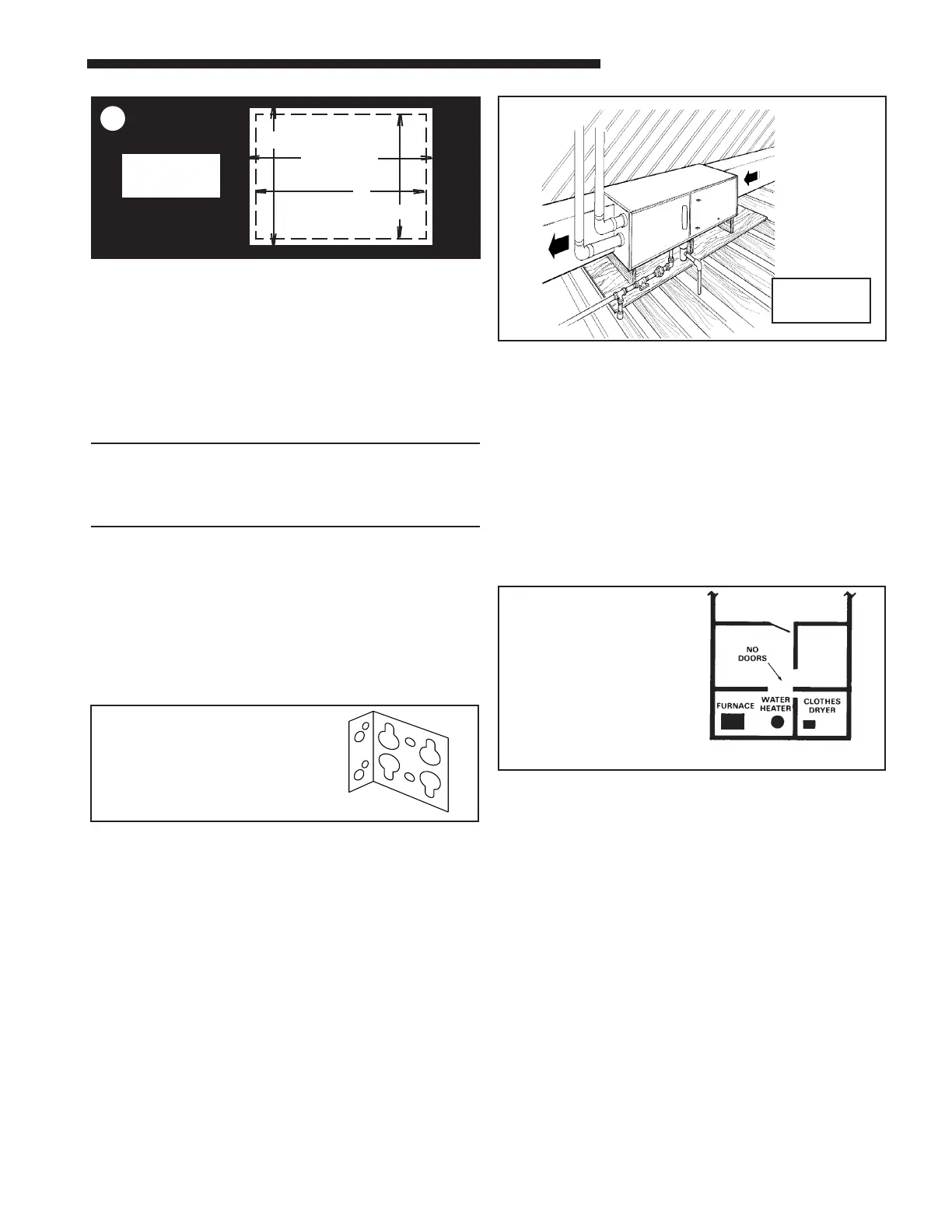
The furnace may be installed in an attic or crawl space in
the horizontal position by placing the furnace on the left
side (as viewed from the front in the vertical position). The
horizontal furnace installation in an attic should be on a
service platform large enough to allow for proper clearances
on all sides and service access to the front of the furnace
(See Figure 3 & Clearance Table 1). Line contact is only
permissible between lines formed by intersections of the
top and two sides of the furnace casing and building joists,
studs, or framing.
The furnace may be placed horizontally in a crawl space on
a pad or other noncombustible material which will raise the
unit for sufficient protection from moisture. The furnace
must be supported at both ends and the middle when
installed horizontally.
The furnace must also be elevated a minimum of 6
inches to allow clearance for the condensate drain to
exit the cabinet in the horizontal position.
The horizontal furnace may also be suspended from the
joists using 3/8" all-thread rods with pieces of angle iron
underneath the furnace to form a hanging rack at both
ends and the midpoint. The rods need to be of sufficient
length to allow for proper clearances from combustible
materials. The angle iron needs to be at least 32" in length
to allow for access to service panels.
50 CU. FT. OR MORE
PER 1000 BTU/HR. INPUT
ALL EQUIP. INSTALLED
UNCONFINED
6
AIR FOR COMBUSTION AND VENTILATION
If these furnaces are installed in a nondirect vent capac-
ity then the adequate flow of combustion and ventilating
air must not be obstructed from reaching the furnace. Air
openings provided for combustion air must be kept free of
obstructions which restrict the flow of air. Airflow restric-
tions affect the efficiency and safe operation of the furnace.
Keep this in mind should you choose to remodel or change
the area which contains your furnace. Furnaces must have
a free flow of air for proper performance.
Provisions for combustion and ventilation air shall be made
in accordance with latest edition of Section 5.3, Air for Com-
bustion and Ventilation, of the National Fuel Gas Code,
ANSI Z223.1 — CAN/CGA B149.1 or applicable provisions
of the local building codes. Special conditions created by
mechanical exhausting of air and fireplaces must be con-
sidered to avoid unsatisfactory furnace operation.
5
UPFLOW/
HORIZONTAL
SHOWN
 Loading...