6 18-GE01D1-9
Installer’s Guide
NOTE:
Torque specification for TXV equals 1/6 turn past finger
tight.
3. Run refrigerant tubing into the stub sockets of in-
door unit coil.
4. Braze and evacuate according to indoor and outdoor
installation instructions.
PAINTED AREAS OF UNIT MUST BE SHIELDED DUR-
ING BRAZING
▲
WARNING
!
TO PREVENT INJURY OR DEATH DUE TO ELECTRICAL
SHOCK OR CONTACT WITH MOVING PARTS, LOCK
UNIT DISCONNECT SWITCH IN OPEN POSITION
BEFORE SERVICING UNIT.
F. CONDENSATE DRAIN PIPING
NOTE:
Make certain that the unit has been installed in a level
position to ensure proper draining.
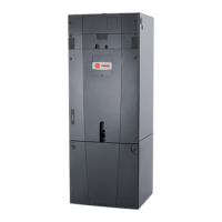
3/4" NPT Secondary
drain connection
3/4" NPT Primary
drain connection
Figure 6
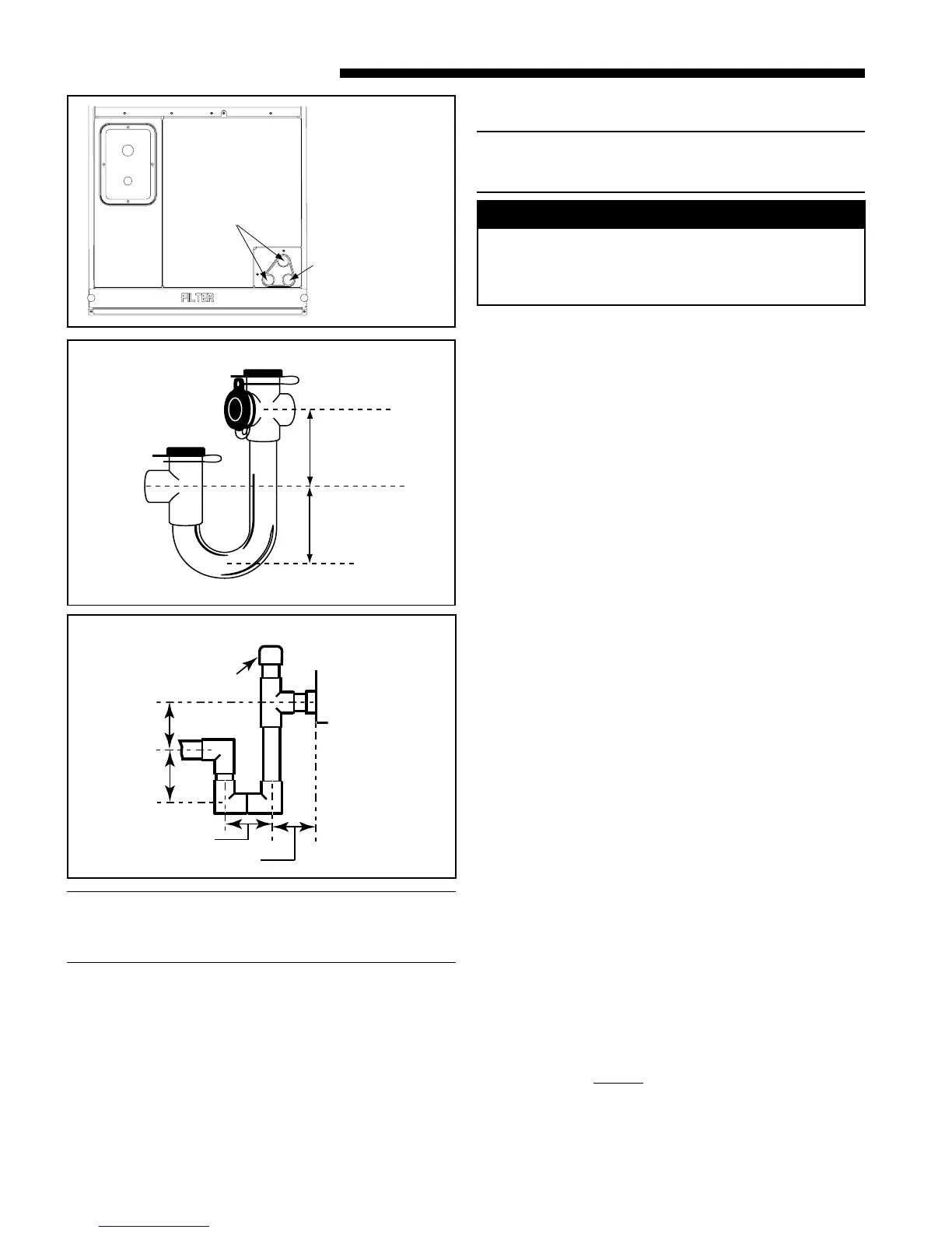
Field fabricated trap
2" MINIMUM
2" MINIMUM
Manufactured traps
EZT-105
2" MIN.
2" MIN.
CAP OR PLUG
Trap must be within 4'
of air handler condensate
drain connection.
Close as possible
Figure 7
Figure 8
The indoor blower is downstream of the evaporator coil
which creates a negative pressure at the condensate
drain connections during operation. The condensate
drain connections in front of the indoor coil are 3/4"
NPT. The lower connection is the primary drain. See
Figure 6.
Two secondary drain connections are provided for the
different orientations (See Figure 6). The lower of the
two should be connected as a backup to prevent conden-
sate overflow by a blocked primary drain.
For proper drainage of condensate, the following steps
should be followed:
1. The primary drain line must be trapped with a
minimum of 2" water seal as shown in Figures 7 & 8.
Do not use preformed 3/4" PVC running traps.
The use of Field fabricated or manufactured traps
as shown in Figures 7 & 8 is acceptable. The
manufactured trap shown in Figure 7 allows for a
float switch option to be added.
Refer to the manufacturers data and instructions
for details.
2. The trap must be located within 4 feet of the air
handler drain outlet connection.
3. It is recommended that a clean-out tee or cross be
installed in the primary drain line for future mainte-
nance (See Figure 7 & 8).
4. Do not use reducing fittings in the condensate drain
lines.
5. Slope the drain lines downward a minimum of 1/4"
per foot.
6. Insulate the primary drain to prevent sweating.
7. Provide means for drainage to prevent winter
freeze-up of condensate line.
8. Do not connect the drain line to a closed drain system.
9. Use Teflon
®
tape on the air handler drain line
connections!
Do Not Use pipe joint compound or
PVC/CPVC cement!

 Loading...