18-GE01D1-9 7
Installer’s Guide
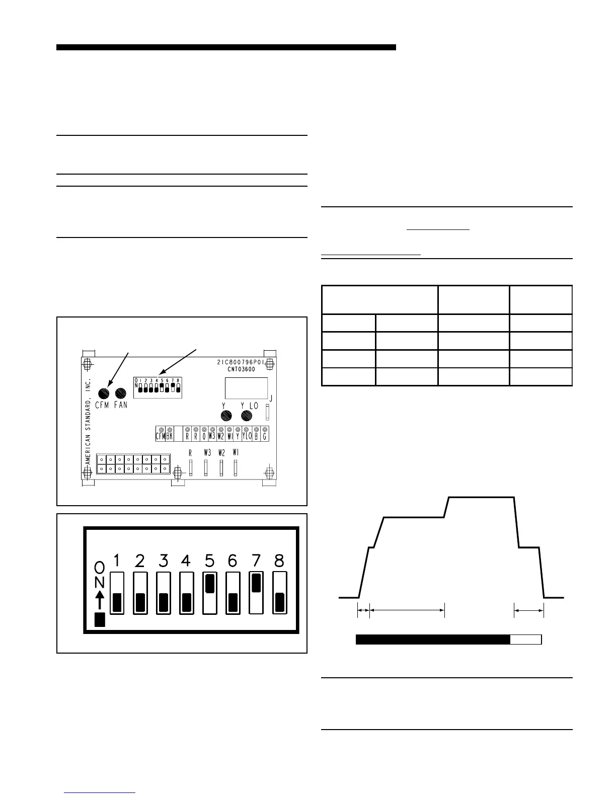
COOLING OFF - DELAY OPTIONS
SWITCH SETTINGS SELECTION
NOMINAL
AIRFLOW
5 - OFF 6 - OFF NONE SAME
5 - ON 6 - OFF 1.5 MINUTES 100% *
5 - OFF 6 - ON 3 MINUTES 50%
5 - ON 6 - ON ENHANCED** 50 - 100%
* - This setting is equivalent to the BAY24X045 relay benefit
** - This ENHANCED MODE selection provides a ramping up
and ramping down of the blower speed to provide improved
comfort, quietness, and potential energy savings. The graph
shows the ramping process.
It is always recommended that an auxiliary drain pan
be installed under a horizontally installed air handler.
Connect the auxiliary drain line to a separate drain line
(no trap is needed in this line) and terminate according
to local codes.
NOTE:
DO NOT use a torch or flame near the plastic drain pan
coupling.
NOTE:
DO NOT tighten the drain pipe excessively. Support the
condensate piping and traps outside the unit to prevent
strain on the drain coupling.
G. ELECTRICAL — POWER WIRING
1. These Air Handlers are shipped from the factory
wired for 230 volts. The units may be wired for 208
volts. Follow instructions on unit wiring diagram lo-
DIP SWITCHES (AS SHIPPED)
COOLING
HEATING
AIRFLOW
FAN OFF
DELAY
AUXILIARY
HEAT SPEEDS
0
OFF OFF
50%
80%
100% if necessary
50%
Dehumidify
Fast Coil Cooling
and Heating
Efficiency
7.5
minutes
3
minutes
1
minute
FAN OPERATION (CFM)
COMPRESSOR OPERATION ON
OFF
as required
NOTE:
Direct drive motors have bearings which are permanently
lubricated and under normal use lubrication is not recom-
mended.
From Dwg. 800796a
CFM
SELECTION
LIGHT
DIP
SWITCHES
ICM FAN CONTROL
Figure 9
cated on blower housing and in the Service Facts
document included with the unit.
2. The selection of wire and fuse sizes should be made
according to the Minimum Branch Circuit Ampacity
and the Maximum Overcurrent Device listed on the
unit nameplate.
3. Field wiring diagrams for electric heaters and unit
accessories are shipped with the accessory.
4. Wiring must conform to National and Local codes.
Ground unit per Local codes with good safety proce-
dures.
If an electric heater is not installed, connections are
made through the 7/8" knockout into the air handler
junction box to the two power leads and ground wire
connections which are located near the discharge of the
blower
NOTE:
If air handler is used
with or without a heater, the 7/8"
electrical entry hole as well as any other cabinet penetrations
must be sealed air tight.

 Loading...