18-CD19D5-25 27
Installer’s Guide
CONDENSATE DRAIN INSTRUCTIONS
▲
CAUTION
!
IT IS RECOMMENDED THAT A DRAIN PAN BE INSTALLED
UNDER THE FURNACE TO PREVENT PROPERTY DAMAGE,
PERSONAL INJURY OR DEATH FROM LEAKING CONDEN-
SATE.
VERTICAL APPLICATIONS
Upflow furnace - The connection tubing for left and
right side drainage is shipped in the blower compart-
ment. Install the connection tubing from the trap to the
side of the unit and trim all excess tubing to avoid
kinks.
Downflow furnace - The furnace is shipped with the
left side drainage setup. To change the right side drain,
remove the drain lines from the trap, rotate the trap
180° so it exits to the right, reconnect the lines, and run
a 1/2" CPVC pipe from the trap out through the right
side knock-out. Use RTV silicone sealant to connect the
CPVC pipe to the trap for ease of removing to clean the
trap.
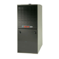
When the factory supplied “off-set” (2X3 reducing cou-
pling) is used for 3” vent pipe installation, make sure
the marking “Top” is located on the top side of the pipe.
The straight side must be on bottom for proper conden-
sate drainage. This coupling is factory supplied only with
the following models: UC120 & DC120, UX120 & UY120,
UX100 & UY100, UX808C960, and All DX & DY models.
LABEL
SAYS
"TOP"
STRAIGHT SIDE MUST BE
ON BOTTOM FOR PROPER
CONDENSATE DRAINAGE.
WHEN THE FACTORY SUPPLIED "OFF-SET" (2X3
REDUCING COUPLING) IS USED FOR 3" VENT PIPE
INSTALLATION, MAKE SURE THE MARKING "TOP" IS
LOCATED ON THE TOP SIDE OF THE PIPE.
2" TO 3" COUPLING
FURNACE
VENT
OUTLET
FACTORY SUPPLIED ONLY WITH
THE FOLLOWING MODELS:
UC120 & DC120
UX120 & UY120
UX100 & UY100
UX080C960
ALL DX & DY MODLES
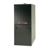
Right side
UPFLOW (VERTICAL)
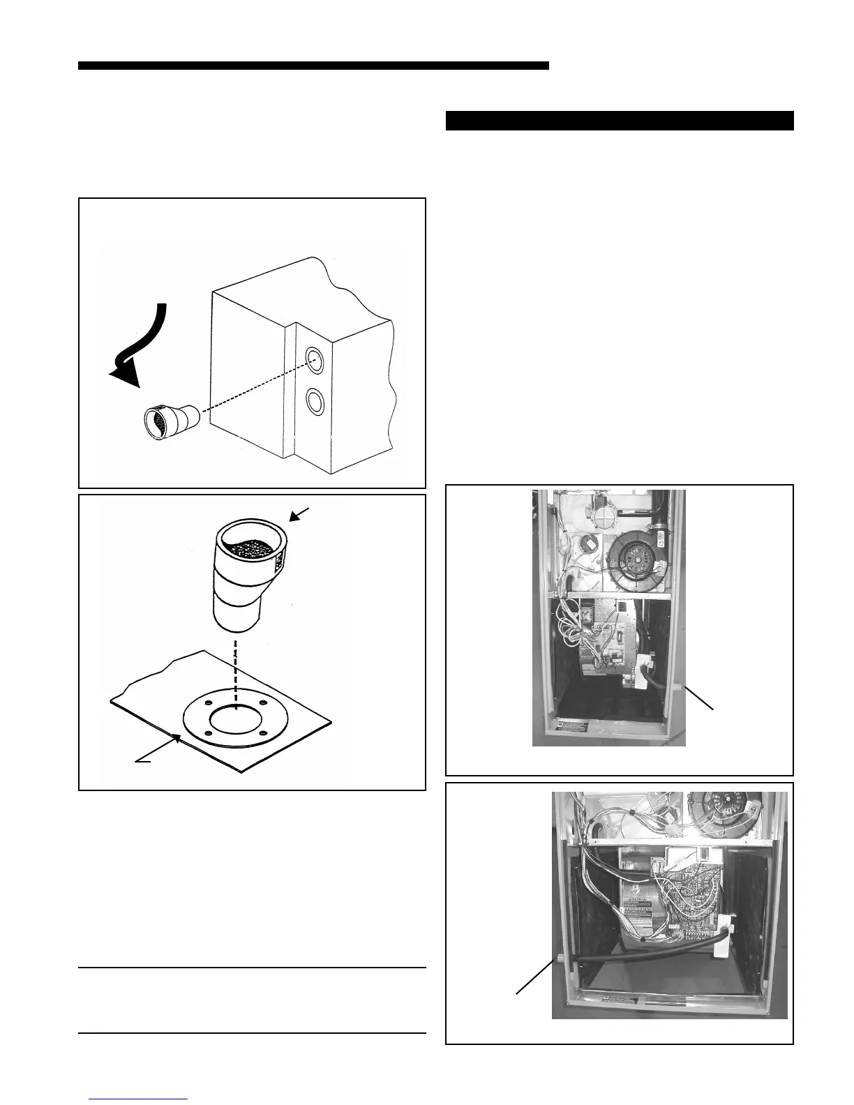
UPFLOW (VERTICAL)
Left side
DIRECTION OF STAINLESS STEEL FITTING
All stainless steel fitting must be installed with male
end towards the furnace.
All horizontal stainless steel sections must be posi-
tioned with the seam on top.
All long horizontal sections must be supported to pre-
vent sagging.
All pipe joints must be fastened and sealed to prevent
escape of combustion products into the building.
NOTE:
Both venting methods shown in Figure 40 & 42 must
also have the combustion air inlet installed - meeting
dimension requirements of Figure 36.
#
$
%
^
 Loading...