18-CD19D5-25 35
Installer’s Guide
IMPORTANT:
Reinstall the propane orifices to the same depth as the
orifices supplied with the equipment.
See Table 18 for help in selecting orifices if orifice
change is required. Furnace input rate and tempera-
ture rise should be checked again after changing ori-
fices to confirm the proper rate for the altitude.
Installations above 4,000 feet may require a pressure
switch change. If required, use the BAYHALT*** Kit
(High Altitude Accessory Kit) listed in PRODUCT DATA.
PART NUMBERS FOR REPLACEMENT ORIFICES
DRILL
SIZE
PART
NUMBER
DRILL
SIZE
PART
NUMBER
44
45
46
47
48
49
50
ORF00501
ORF00644
ORF00909
ORF00910
ORF01099
ORF00503
ORF00493
54
55
56
57
58
59
ORF00555
ORF00693
ORF00907
ORF00908
ORF01338
ORF01339
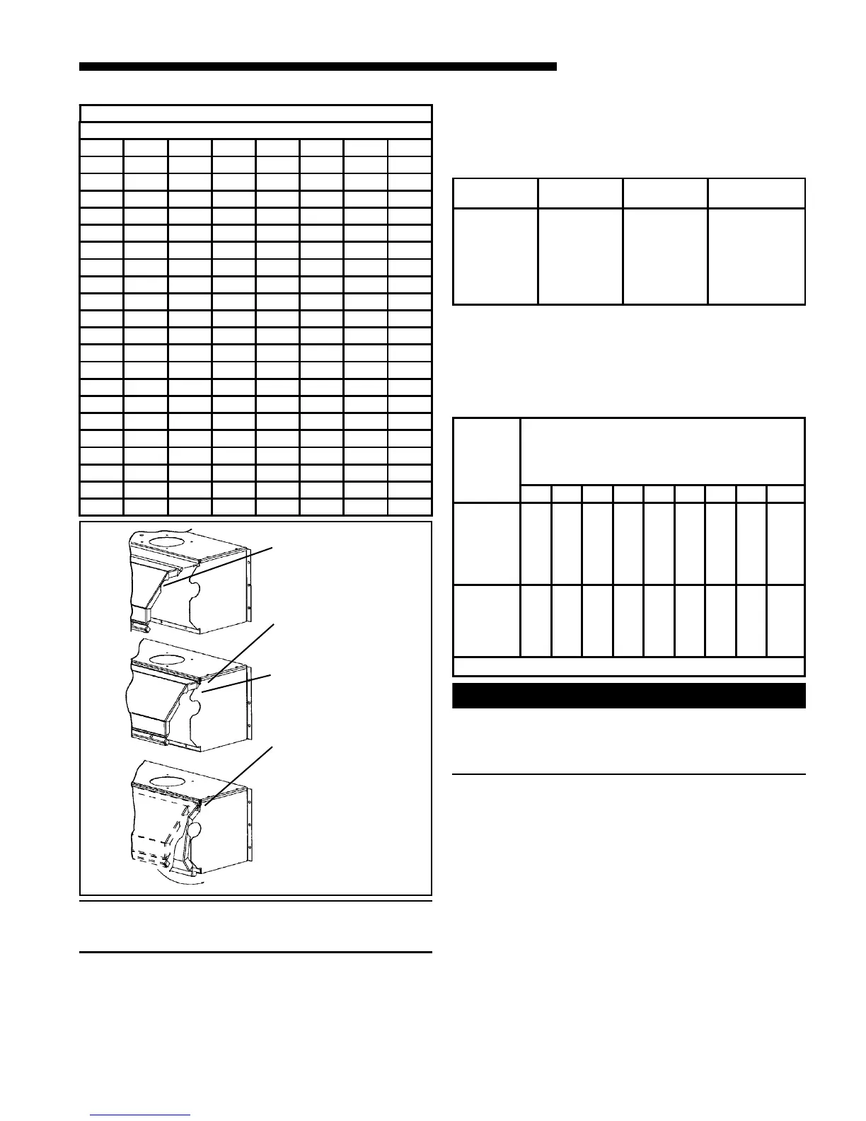
REINSTALLATION OF THE BURNER BOX COVER
Figure 55 shows the correct way to reinstall the burner
box cover if adjustment or replacement of the flame
sensor, hot surface igniter, or main burner orifices have
required removal of the cover.
TABLE 17
Orifice
Twist Drill
Size If
Installed
At Sea
Level
ALTITUDE ABOVE SEA LEVEL
and Orifice Required At Other Elevations
2000 3000 4000 5000 6000 7000 8000 9000 10000
42
43
44
45
46
47
42
44
45
46
47
48
43
44
45
47
47
48
43
44
45
47
47
49
43
45
46
47
48
49
44
45
47
48
48
49
44
46
47
48
49
50
45
47
48
49
49
50
46
47
48
49
50
51
47
48
50
50
51
52
54
55
56
57
58
54
55
56
58
59
55
55
56
59
60
55
55
57
59
60
55
56
57
60
61
55
56
57
60
62
55
56
58
61
62
56
56
59
62
63
56
56
59
63
63
56
57
60
63
64
From National Fuel Gas Code - Table F-4
WARNING
!
CARBON MONOXIDE POISONING HAZARD
Failure to follow the installation instructions for the
venting system being placed into operation could
result in carbon monoxide poisoning or death.
START UP AND ADJUSTMENT
PRELIMINARY INSPECTIONS
With gas and electrical power “OFF”
1. Duct connections are properly sealed
2. Filters are in place
3. Venting is properly assembled
4. Blower door is in place
Flip the switch on main gas valve within the unit to the
“OFF” position. Turn the external gas valve to “ON”.
Purge the air from the gas lines. After purging, Check
all gas connections for leaks with a soapy solution —
DO NOT CHECK WITH AN OPEN FLAME.
Allow 5 minutes for any gas that might have escaped to
dissipate. LP Gas being heavier than air may require
forced ventilation. Flip the switch on the gas valve in
the unit to the “ON” position.
TABLE 16
GAS FLOW IN CUBIC FEET PER HOUR
2 CUBIC FOOT DIAL
SEC. FLOW SEC. FLOW SEC. FLOW SEC. FLOW
8 900 29 248 50 144 82 88
9 800 30 240 51 141 84 86
10 720 31 232 52 138 86 84
11 655 32 225 53 136 88 82
12 600 33 218 54 133 90 80
13 555 34 212 55 131 92 78
14 514 35 206 56 129 94 76
15 480 36 200 57 126 96 75
16 450 37 195 58 124 98 73
17 424 38 189 59 122 100 72
18 400 39 185 60 120 104 69
19 379 40 180 62 116 108 67
20 360 41 176 64 112 112 64
21 343 42 172 66 109 116 62
22 327 43 167 68 106 120 60
23 313 44 164 70 103 124 58
24 300 45 160 72 100 128 56
25 288 46 157 74 97 132 54
26 277 47 153 76 95 136 53
27 267 48 150 78 92 140 51
28 257 49 147 80 90 144 50
TABLE 16
T
ROTATE THE FRONT
COVER INWARD
MAKING SURE THAT
ALL SIDE FLANGES
ARE OUTSIDE OF THE
BOX.
INSERT THE TOP
FLANGE OF THE FRONT
COVER UNDER THE LIP
INSIDE THE BOX
ALL SIDE FLANGES
MUST BE OUTSIDE OF
THE BOX
ROTATE THE FRONT
COVER AS SHOWN
 Loading...