8 UHM-DHM-SF-1H
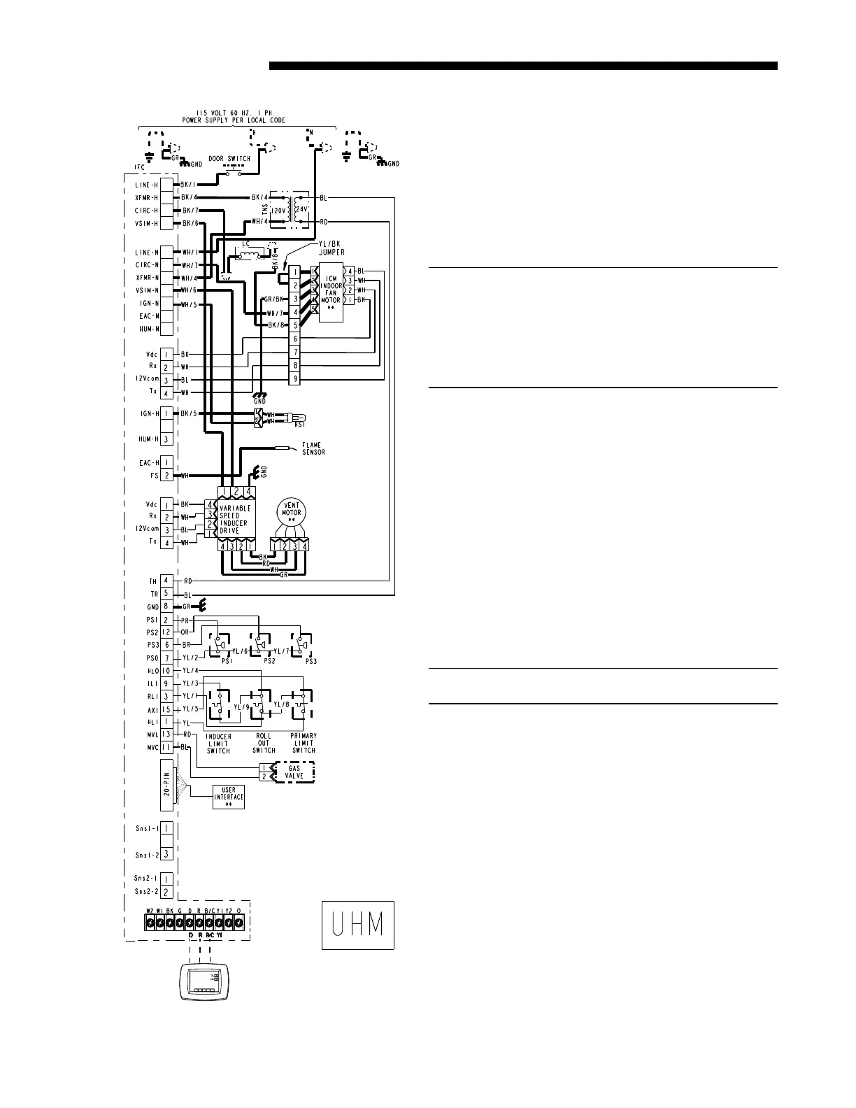
Service Facts
NOTE: Y1 is output to non-communicating outdoor
unit
1
2
3
4
5
6
7
8
9
10
11
12
13
14
15
16
17
Communicating
Comfort Control
SEQUENCE OF OPERATION
SEQUENCE OF OPERATION – COMMUNICATING
MODE
1. This furnace is fully modulating between 40% and
100% of capacity in 1% increments. The furnace
always lights at approximately 65% and will
modulate up or down; depending on the commu-
nicating comfort control demand. Requested
capacity can be seen in the “STATUS” section of
the User Interface menu.
Note:
Pressure Switch 1 closes at approximately 40%
of capacity.
Pressure Switch 2 closes at approximately 65%
of capacity.
Pressure Switch 3 closes at approximately 95%
of capacity.
2. The communicating comfort control signals the
furnace IFC for heat.
3. The IFC then checks all safeties, thermostats, and
pressure switches PS1, PS2, and PS3.
4. The IFC signals the variable speed inducer drive
to start the vent motor at the speed needed to
close pressure switches PS1 and PS2.
5. PS1 and PS2 close.
6. The IFC receives a 24 VAC signal from PS1 and
PS2 when they close. This verifies the vent
motor is moving the correct amount of combus-
tion air through the furnace and the vent system.
7. IFC starts the hot surface ignitor learning routine
warm-up time cycle.
8. IFC turns on the gas valve. Trial time for ignition
is 5 seconds.
Note:
The furnace lights at approximately 65% of capacity.
9. The IFC verifies ignition by the flame current
sensing method. If a flame is not detected, the
IFC will cycle the furnace three times to try and
verify a flame. If no flame is detected, the IFC
will lockout for one hour.
The IFC will send an alert code to the communi-
cating comfort control and User Interface. The
Red alert LED two times repeatedly.
10. If a flame is detected, the IFC will start the heat
exchanger warm-up time delay for the indoor
blower.
11. “IGNITION” will now be displayed in the “STA-
TUS” section of the User Interface menu.
12. After 45 seconds, the IFC signals the indoor
blower motor to run at the programmed ignition
sequence speed.
13. Depending on the communicating comfort control
demand, the IFC will then signal the variable
speed inducer motor drive board and the indoor
blower motor to ramp up or down.
5
 Loading...