18-BC92D1-1F-EN
7
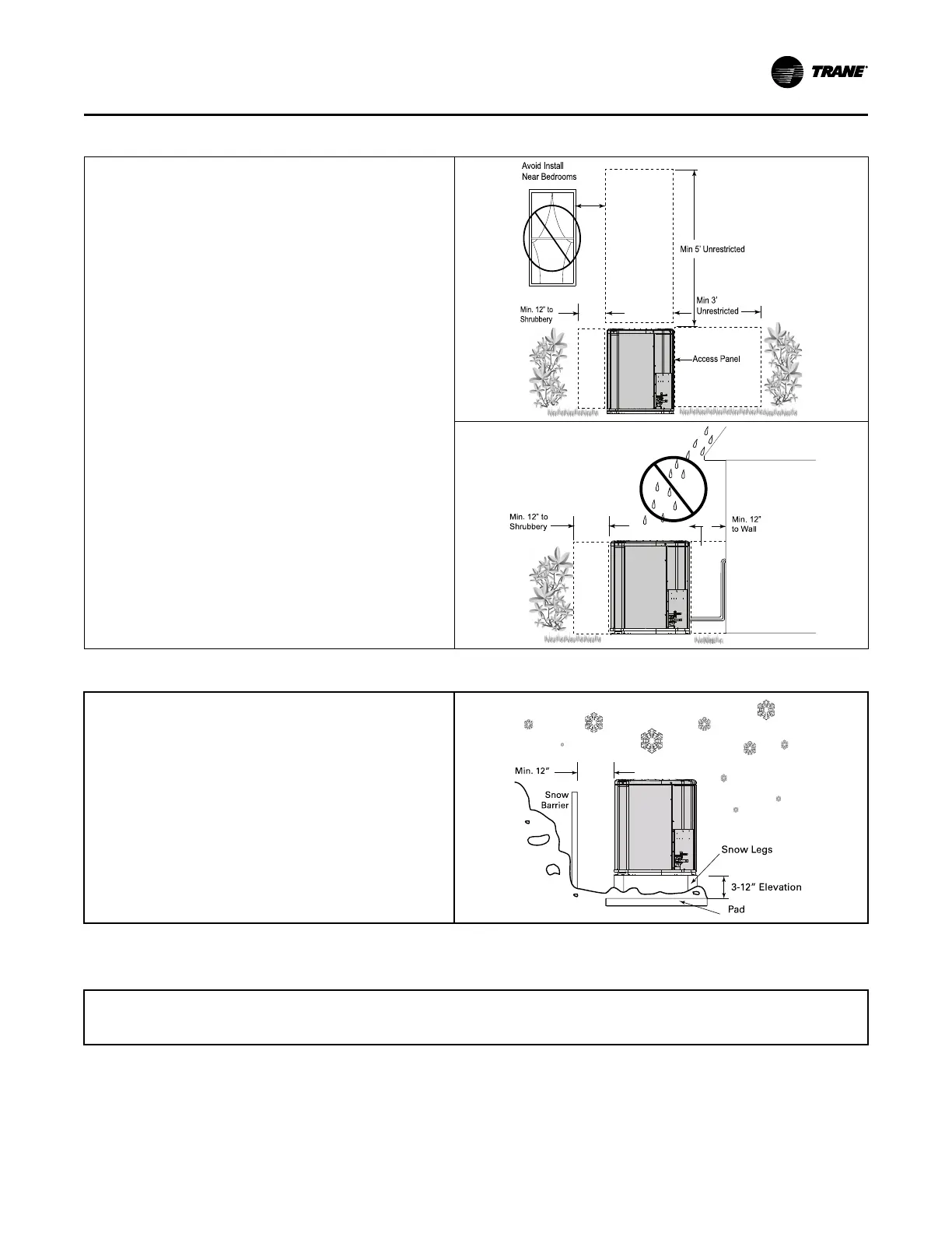
Table 5. Suggested Locations for Best Reliability
• Ensure the top discharge area is unrestricted for at least 5
feet above the unit.
• Provide at least 3 feet clearance in front of the control box
(access panels) and any other side requiring service.
• Do not locate close to bedrooms as operational sounds may
be objectionable.
• Avoid locations near windows and similar areas where
condensation and freezing defrost vapor can annoy a
customer.
• Position the outdoor unit a minimum of 12” from any wall or
surrounding shrubbery to ensure adequate airflow.
• Outdoor unit location must be far enough away from any
structure to prevent excess roof runoff water or icicles from
falling directly on the unit.
• Position the outdoor unit a minimum of 12” from any wall or
surrounding shrubbery to ensure adequate airflow.
• Outdoor unit location must be far enough away from any
structure to prevent excess roof runoff water or icicles from
falling directly on the unit.
Min. 12” to
Shrubbery
Avoid Install
Near Bedrooms
Min 5’ Unrestricted
Acce ss Panel
Min 3’
Unrestricted
Min. 12” to
Shrubbery
Min. 12”
to Wall
Table 6. Cold Climate Considerations (Heat Pump Only)
Note: It is recommended that these precautions be taken for
units being installed in areas where snow accumulation and
prolonged below-freezing temperatures occur.
• Units should be elevated 3–12 inches above the pad or
rooftop, depending on local weather. This additional height
will allow drainage of snow and ice melted during defrost cycle
prior to its refreezing. Ensure that drain holes in unit base pan
are not obstructed, preventing drainage of defrost water.
• If possible, avoid locations that are likely to accumulate snow
drifts. If not possible, a snow drift barrier should be installed
around the unit to prevent a build-up of snow on the sides of
the unit.
Min. 12”
Snow
Barrier
3-12” Elevation
Snow L egs
Pad
Coastal Considerations
If installed within one mile of salt water, including seacoasts and inland waterways, models without factory supplied Seacoast Salt Shields
require the addition of BAYSEAC001 (Seacoast Kit) at installation time.
UUnniitt LLooccaattiioonn CCoonnssiiddeerraattiioonnss
 Loading...


