VAV-SVX08R-EN
25
single row coils. For multi-row coils, always plumb
in counter flow orientation.
• Water inlet is always on the airflow downstream
side of the hot water coil.
• Water outlet is always on the upstream side of
the hot water coil.
3. Care should be taken to properly support the water
coil piping connections while connecting the
adjoining pipe.
4. It is recommended that piping to the water coil
should be done after field-mounted controls,
external insulation, and ductwork connections have
been completed.
IImmppoorrttaanntt:: Do not connect water valve or pipe
extensions to the water coil connections
unless supported.
Discharge Duct Temperature
Sensor Installation
NNoottee:: TThhiiss pprroocceessss iiss ttoo bbee uusseedd ffoorr ccoonnttrrooll
sseeqquueenncceess tthhaatt iinnvvoollvvee DDiisscchhaarrggee AAiirr
TTeemmppeerraattuurree ((DDAATT)) ccoonnttrrooll..
Several Tracer® UC210/UC400 control sequences
perform direct DAT control of the VAV unit when both
modulating unit heat and modulating ECM fan are
present or when modulating unit heat is present on a
non-fan-powered VAV unit. Supported modulating unit
heat options include modulating hot-water and SCR-
controlled electric heat. In these Tracer® UC210/UC400
control sequences, the DAT is a control input to the unit
controller.
NNoottee:: Optional factory mounted discharge duct
temperature sensors available with modulating
unit heat control.
IImmppoorrttaanntt:: To ensure good control of the DAT and
overall level of heat being supplied to the
zone, it’s critical to locate the DAT sensor in
a location in the downstream ductwork that
is not too close to the heating water or
electric coils.
1. Locate mounting location for DAT sensor a
minimum of 1.5 equivalent duct diameters
downstream of the heating coils and midway
between top and bottom on the side of the
ductwork.
2. Mount the DAT sensor using the instructions
provided at the end of this manual.
3. If not already factory wired to unit controller, wire
DAT sensor to unit controller using unit schematic.
Electronic Duct Temperature
Sensor Installation
Visually inspect the sensor unit and harness for
damage. Return damage or defective products.
Tools required for installation:
• Cutter to release zip tie
• DVM (Digital Volt ohm Meter)
• Appropriate screw driver for mounting screws
• Appropriate drill and drill bit for mounting screws
NNootteess::
• Installer must be a qualified, experienced
technician.
• Cut loose harness, verify location.
• Avoid location where excessive vibration,
moisture, corrosive fumes or vapors are
present.
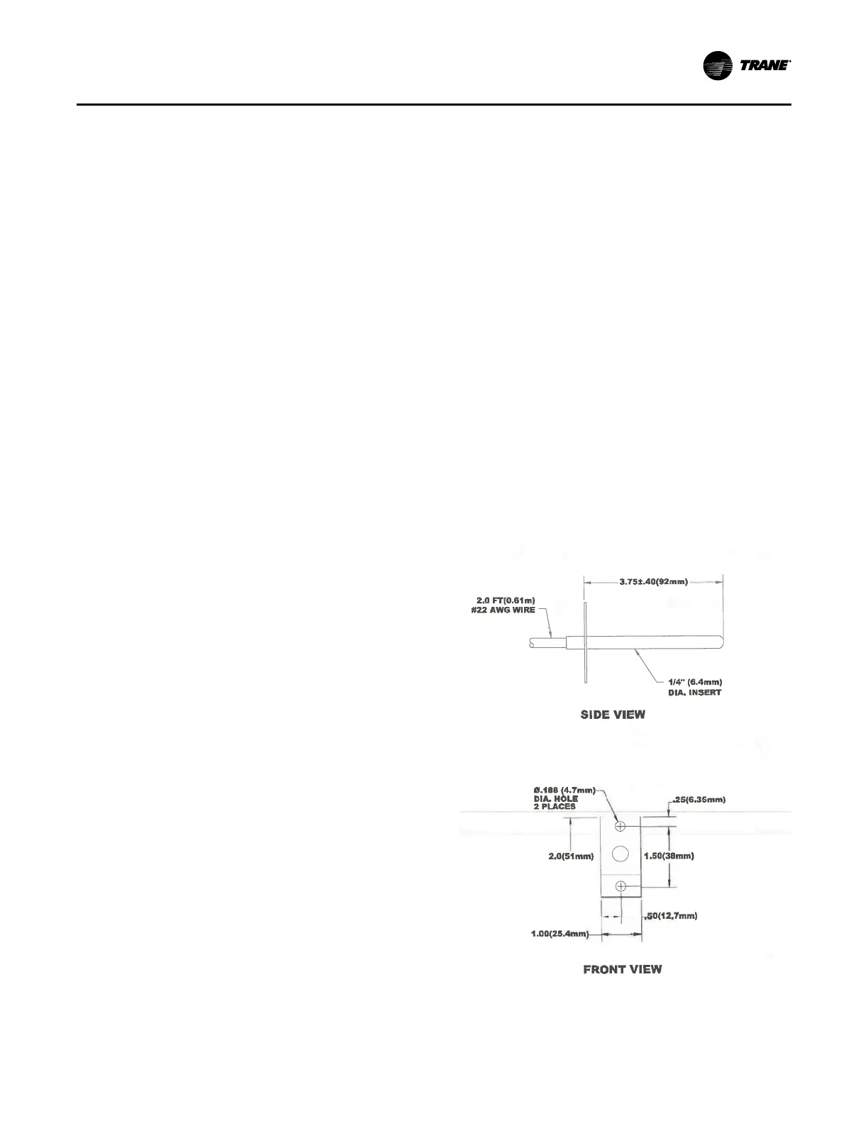
1. Determine the sensor mounting location on the
duct. The sensing element is located within 1 inch
(25mm) of the end of the sensing probe, and it
should be located in the air stream typical of the
temperature requiring sensing.
2. Use the mounting plate supplied as a template (or
refer to Figure 18, p. 25 for duct mounting
dimensions) for mounting hole location.
Figure 18. Mounting dimensions
3. Mount the sensor to the duct using (2) #8–1/6 x 1/2–
in sheet metal screws.
UUnniitt IInnssttaallllaattiioonn
 Loading...