16
VAV-SVX08R-EN
Dual-Duct VAV Units
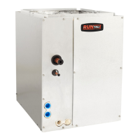
Dual-duct units provide two air valves: one as heating
primary air and the other as cooling primary air. Both
discharge into the common outlet, which leads to the
zone being controlled. See Figure 2, p. 16.
Units are provided with a slip and drive rectangular
duct connection or can be ordered with integral outlet
plenum.
Sequencing of hot and cold air valve is dependent on
job requirements. One typical control is valves working
in conjunction to respond to zone temperature.
When the cooling valve becomes fully closed or
reaches a specified minimum, the heating valve will
begin to modulate or vice versa. The typical result is
that air flowing to the zone varies from maximum
down to a minimum and back up to maximum as load
varies and controls would cause one air valve to close
and the other to open.
Another typical application is when the unit provides a
constant volume to the zone. When the zone sensor is
tied directly to the heating valve, it will modulate the
heating valve according to the zone temperature.
When the heating valve is fully closed or there is a call
for cooling in the zone, the cooling valve will be at
constant supply. As the space becomes too cool, the
heating valve will modulate open, decreasing the
cooling valve flow. The typical result is that the air
flowing into the zone stays at a constant flow whether
the unit is heating or cooling.
Factory-installed Trane unit controls available include;
• UC400 — one required per unit
• VV550 — two required per unit
• UCM — two required per unit
Figure 2. Typical dual-duct unit; VDDF
Fan-Powered/Fan-Powered Low-
Height VAV Units
VariTrane™ fan-powered and low-height fan-powered
units can be either parallel or series, with or without re-
heat. Refer to the following figures.
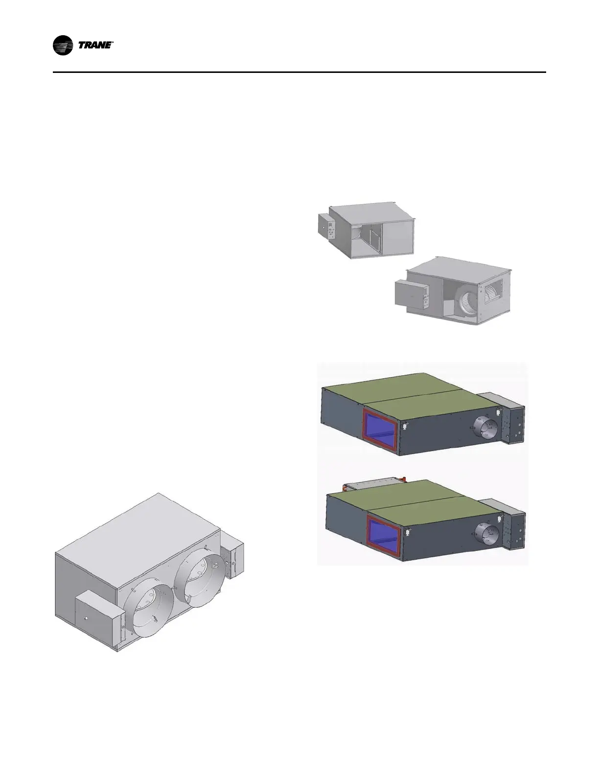
Typical Fan-powered Units
Figure 3. Parallel fan-powered terminal unit (top) and
series fan-powered terminal units (bottom)
Figure 4. Low height series: LSCF (top) and low
height series: LSWF (bottom)
UUnniitt IInnffoorrmmaattiioonn
 Loading...