20
VAV-SVX08R-EN
Table 1. Dual duct VAV unit hanger location
dimensions
Inlet
Size
(in)
A B C
in
mm
in
mm
in
mm
5 thru
10
23.15 588 25.25 641 1.38 35
12 thru
16
23.15 588 37.25 946 1.38 35
Fan-Powered VAV Units and
Chilled Water Sensible Cooling
Terminal Units
Fan-powered (standard and low-height) and chilled
water sensible cooling terminal units should be
supported by either hanger straps or by using a
threaded rod in conjunction with the hanger brackets
that are provided on the unit. Care should be exercised
to insure that the hanging straps do not block the side
access panel. Refer to the following figures.
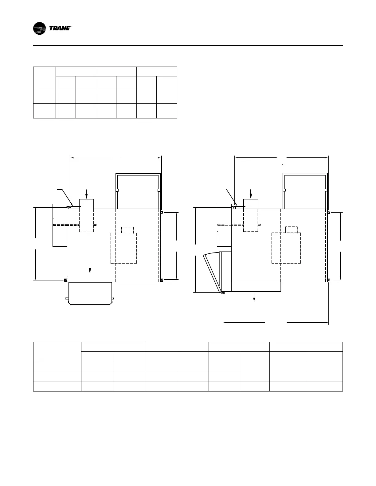
Bracket Locations — Fan Powered
Figure 12. Parallel hanger bracket location sizes
BB
Primary
Airow
Primary
A
irow
Air
Valve
Air
Valve
Flow Ring
tubing
Flow Ring
tubing
OPTIONAL
SUPPRESSOR
OPTIONAL
SUPPRESSOR
C
Airflow
Discharge Outlet
Airflow
Discharge Outlet
Heater
Water Coil
Terminal Box
A
A
43.546
(1106 mm)
D
Table 2. Parallel hanger bracket location dimensions
Fan Size
A B C D
in.
mm
in.
mm
in.
mm
in.
mm
02SQ 26.75 679 38.95 989 28.95 735 37.10 942
03SQ, 04SQ, 05SQ 29.75 756 38.95 989 31.45 799 39.70 1008
06SQ, 07SQ 36.75 933 38.95 989 38.95 989 47.10 1196
UUnniitt IInnssttaallllaattiioonn
 Loading...