FILTER iNSTALLATiON
AIR FILTERS TABLE 4
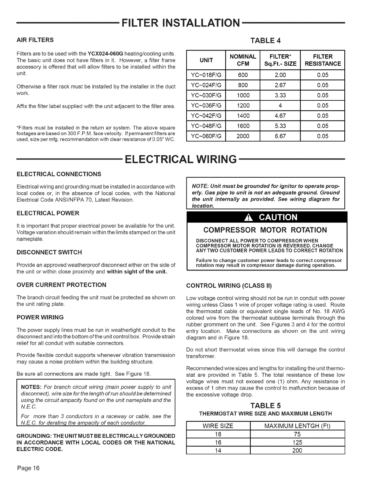
Filters are to be used with the YCX024=060G heating/cooling units.
The basic unit does not have filters in it. However, a filter frame
accessory is offered that will allow filters to be installed within the
unit.
Otherwise a filter rack must be installed by the installer in the duct
work,
Affix the filter label supplied with the unit adjacent to the filter area.
*Filters must be installed in the return air system. The above square
footages are based on 300 F.PM. face velocity. If permanent filters are
used, size per mfg. recommendation with clear resistance of 0.05" WC.
NOMINAL FILTER* FILTER
UNIT
CFM Sq.Ft.- SIZE RESISTANCE
YC~018F/G 600 2.00 0.05
YC~024F/G 800 2.67 0.05
YC~030F/G 1000 3.33 0.05
YC~036F/G 1200 4 0.05
YC~042F/G 1400 4.67 0.05
YC~048F/G 1600 5.33 0.05
YC~060F/G 2000 6.67 0.05
ELECTRICAL WIRING
ELECTRICAL CONNECTIONS
Electrical wiring and grounding must be installed in accordance with
local codes or, in the absence of local codes, with the National
Electrical Code ANSI/NFPA 70, Latest Revision.
ELECTRICAL POWER
It is important that proper electrical power be available for the unit.
Voltage variation should remain within the limits stamped on the unit
nameplate.
DISCONNECT SWITCH
Provide an approved weatherproof disconnect either on the side of
the unit or within close proximity and within sight of the unit.
NOTE: Unit must be grounded for ignitor to operate prop-
erly. Gas pipe to unit is not an adequate ground. Ground
the unit internally as provided. See wiring diagram for
location.
COMPRESSOR MOTOR ROTATION
DISCONNECT ALL POWERTO COMPRESSORWHEN
COMPRESSOR MOTOR ROTATION IS REVERSED. CHANGE
ANYTWO CUSTOMER POWER LEADS TO CORRECT ROTATION
Failure to change customer power leads to correct compressor
rotation may result in compressor damage during operation.
OVER CURRENTPROTECTION
The branch circuit feeding the unit must be protected as shown on
the unit rating plate.
POWER WIRING
The power supply lines must be run in weathertight conduit to the
disconnect and into the bottom of the unit control box. Provide strain
relief for all conduit with suitable connectors.
Provide flexible conduit supports whenever vibration transmission
may cause a noise problem within the building structure.
Be sure all connections are made tight. See Figure 18.
NOTES: For branch circuit wiring (main power supply to unit
disconnect), wire size forthe length of run should be determined
using the circuit ampacity found on the unit nameplate and the
N.E.C.
For more than 3 conductors in a raceway or cable, see the
N_ acit of each conductor.
GROUNDING: THE UNITMUST BE ELECTRICALLYGROUNDED
IN ACCORDANCE WITH LOCAL CODES OR THE NATIONAL
ELECTRIC CODE.
CONTROL WIRING (CLASS II)
Low voltage control wiring should not be run in conduit with power
wiring unless Class 1 wire of proper voltage rating is used. Route
the thermostat cable or equivalent single leads of No. 18 AWG
colored wire from the thermostat subbase terminals through the
rubber gromment on the unit. See Figures 3 and 4 for the control
entry location. Make connections as shown on the unit wiring
diagram and in Figure 18.
Do not short thermostat wires since this wilt damage the control
transformer.
Recommended wire sizes and lengths for installing the unit thermo-
stat are provided in Table 5. The total resistance of these low
voltage wires must not exceed one (1) ohm. Any resistance in
excess of 1 ohm may cause the control to malfunction because of
the excessive voltage drop.
TABLE 5
THERMOSTAT WIRE SIZE AND MAXIMUM LENGTH
WIRE SIZE MAXIMUM LENTGH (Ft)
18 75
16 125
14 200
Page 16
 Loading...