INSTALLER'S GUIDE
18-HH08D10-2Page 4
Note that all Remote Analog Comfort Sensors must be
connected to the proper zone address on terminal block
TB5 on the Expander Board(s). Either sensor lead can be
connected to the appropriate terminal, ("1/5", "2/6" "3/7" or
"4/8") and the other lead to "C" for that address. All
Communicating Comfort Sensors (digital) connections are
made at the System Controller (S1, S2, R and B) on
Terminal Block TB1). Any combination of Communicating
Comfort Sensors and Analog Temperature Sensors (one
per zone) may be utilized when the Master Scheduler is
applied.
COMFORT SENSOR INSTALLATION:
Refer to the Installer's Guide for the selected Zone Comfort
Sensors. Be careful to locate each Comfort Sensor so that
it will be affected by air being supplied by the damper it is
controlling.
DAMPER INSTALLATION:
Refer to the installer's Guide for the damper being used. If
more than one duct serves a zone and a damper can not be
conveniently located to modulate the air to both supply
ducts, two dampers must be installed and electrically
connected (in parallel) to the same Zone/Bypass Control
Card for correct comfort control of that zone. Include the V.
A. draw of both motors when sizing the 24 volt transformer
for damper motor power. Do not exceed 1.25 Amps per
Zone/Bypass Control Card (30 V. A.).
CHECK OUT:
The zone addresses must be set before the system can
operate.
The system may be operated by the Comfort Sensor by
setting mode and set point for the desired operation (see
Comfort Sensor Owner's Manual). If the Comfort Sensor is
communicating with the System Controller, its light la-
beled "status" will flash at a one second interval indicating
proper operation. Rapid flashing indicates improper com-
munication.
NOTE: The System Controller has a minimum compressor
off time of 5 minutes and a normal minimum compressor
run time of 3 minutes. A test mode is available to bypass the
time delay and operate the system at several speeds. See the
hook-up diagram for your particular combination of equip-
ment for switch settings later in this guide.
NOTE: If the test mode is used, make certain the dip
switches are returned to proper settings after testing is
completed. The test mode is entered by correctly setting the
dip switches on the system controller and cycling the power
to the System Controller off and then back on.
Install the System Controller cover by aligning cover over
the two (2) screw holes in bottom of the enclosure base.
Secure in place with screws.
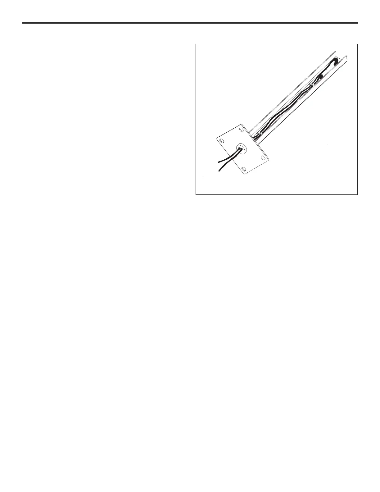
DISCHARGE AIR SENSOR
1 1
1 1
1
DISCHARGE AIR SENSOR
OPERATION:
The Discharge Air Sensor is to be installed in the discharge
(supply) air duct. It senses discharge (supply) air tempera-
ture and sends this signal to the system controller. If the
discharge (supply) air temperature reaches either the
cooling or heating limit programmed into the system
controller, the system will be shut down. If the system is
still calling for heating or cooling when the discharge
(supply) air temperature has reached the preset "resume
operation" value programmed into the system controller,
the system will again operate, provided the minimum "off"
(time delay) has elapsed. The system will operate until: (a)
the system load has been satisfied, or (b) the discharge
(supply) air temperature has again reached the cooling or
heating limit.
SETTINGS:
Settings can be changed with DSW5-6
No settings or calibration required.
SPECIFICATIONS:
The Discharge Air Sensor utilizes a negative temperature
coefficient thermistor. (Resistance decreases as tempera-
ture rises). Nominal resistance @ 77
o
F (25
o
C) = 10,000
ohms. (See Figure 6 for nominal resistance at other
temperatures when checking for defective sensor.)
Maximum ambient temperature 221
o
F (105
o
C).
Operating temperature range 28
o
F to 183
o
F (-2.25
o
C to
83.9
o
C).
Wiring connections 9" (228.6mm) lead wires.
 Loading...