INSTALLER'S GUIDE
18-HH08D10-2 Page 5
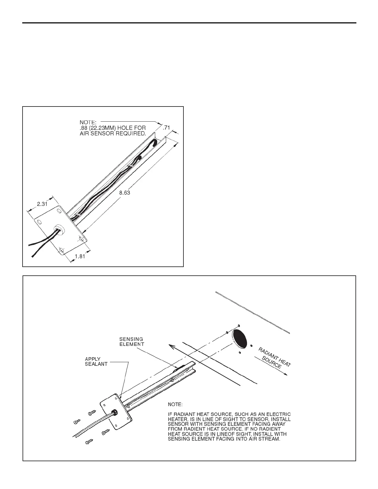
SENSOR POSITIONING
AIRFLOW
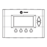
DIMENSIONS
2 2
2 2
2
INSTALLATION:
The Discharge Air Sensor is mounted in the discharge
(supply air) duct by cutting a
7/
8" diameter (22.225mm)
hole in the duct. A hole-saw, Greenlee punch or similar
tool can be used - see Figure 3.
Note: Locate the Discharge Air Sensor in an area of the
discharge, (supply), air duct where laminar flow can be
expected. Avoid dead air areas where representative dis-
charge air temperatures may not exist.
The mounting plate can be used as a template to locate the
four screw holes. Before drilling the four holes, determine
the proper positioning of the sensor as follows: If a radiant
heat source such as an electric heater is in line of sight from
the sensor, position the sensor so that the black thermistor
sensor faces away from the radiant heat source. (This will
prevent a false reading due to the radiant effect on the
thermistor - see Figure 3.)
If no radiant heat source is in line of sight, position the
sensor with the sensing element facing into the air stream
(fastest response). When the proper positioning has been
determined, mark the location of the four holes and drill to
accept #8 sheet metal screws (not furnished).
Apply a circle of caulk sealer (or equivalent) to the duct side
of the sensor mounting plate before mounting to reduce air
leakage.
If a 4" x 4" (106mm x 106mm) electrical box is to be used,
refer to Figure 4. In this case, the caulk sealer is applied
to the duct side of the box as well as to the sensor mounting
plate.
An unobstructed depth of approximately 9" (228.6mm) in
the duct is required in order to accept the sensor probe,
which is approximately 8
3/
4" (222.25mm) in length.
3 3
3 3
3
 Loading...