10253 - 7
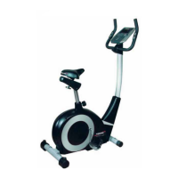
• AttachtheFrontStabilizer(6)ontothefrontcurveplateof
the Main Frame (1) with two M10 Cap Nuts (34), two
M10x57Bolts(35)andtwoØ10BigCurved
Washers (36).
• AttachtheRearStabilizer(4)inthesamemannerasthe
FrontStabilizer(6).
• ConnecttheLeftFootPedal(20)totheLeftCrank(19).
Threaditintothecrankassemblyinacounterclockwise
direction using the tool provided. Connect the Right Foot
Pedal(21)totheRightCrank(19)bythreadingitina
clockwisedirection.
NOTE:TheLeftandRightFootPedals(20,21)andCrank(19)
aremarkedwith“L”&“R”(leftandright).
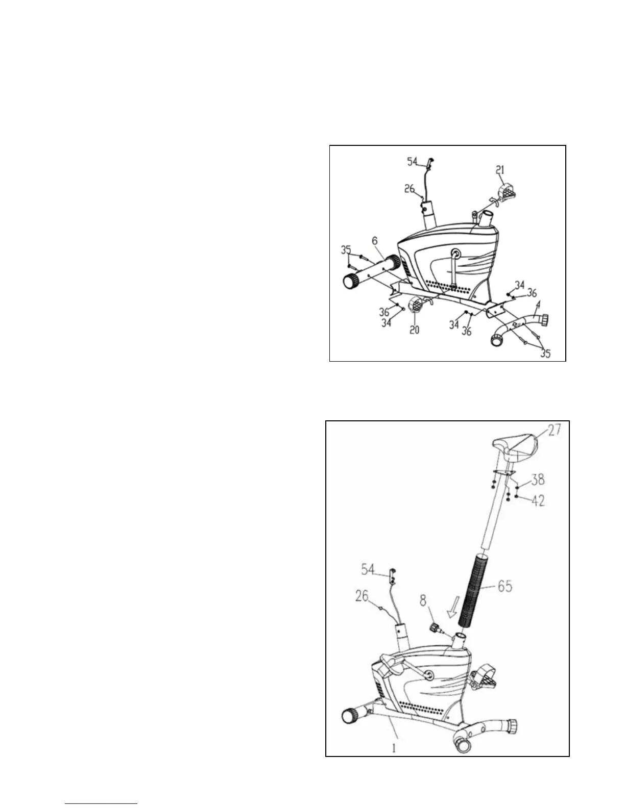
• RemovethreeM8Locknuts(42)andthreeØ8Washers
(38) from underneath the Seat Cushion (27).
• AttachtheSeatCushion(27)ontothetriangleplateofthe
SeatPost(25)withthreeM8Locknuts(42)andthreeØ8
Washers (38) that were previously removed.
• InserttheSeatPost(25)withthePlasticSleeve(65)intothe
bushing on the tube of the Main Frame (1) and then attach
the Round Knob (8) onto the tube of the Main Frame (1) by
turningitinaclockwisedirectiontolocktheSeatPost(25)
in the suitable position.
Adjusting the seat post:
• TurntheRoundKnob(8)inacounterclockwisedirection
until it can be pulled out. Pull out the Round Knob (8)
and then slide the Seat Post (25) up or down to a suitable
position.LocktheSeatPost(25)inplacebyreleasingthe
Round Knob (8) and sliding the Seat Post (25) up or down
slightlyuntiltheRoundKnob(8)“pops”downintothe
lockedposition.Foraddedsafety,tightentheRoundKnob
(8)inaclockwisedirection.
Instructions for assembly
• Unpackthecartonandusingthepartslistcheckthatallpartsareaccountedfor.
• Donotdisposeofthepackagingmaterialuntilassemblyiscompleted.
• Toolsareprovidedforuseinassembly.
4. ASSEMBLY STEPS
STEP 1: STABILIZERS AND PEDAL ASSEMBLY.
STEP 2: SEAT CUSHION AND SEAT POST ASSEMBLY.
 Loading...