ACAUTION
While
the
chipper
chute
is
removed,
do
not
place
your
hands inside the
chipper
blade accessopening.
The
chipper
blade
that
is
located
inside
the
open-
ing
(on
the
chipper
flyWheel)
is
extremely
sharp
and can
cause
serious
personal
injury.
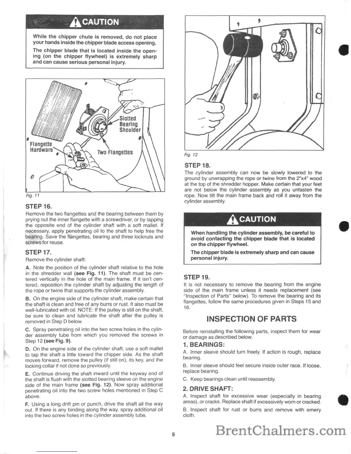
STEP 16.
Remove the two flangettes and the bearing between them by
prying out the inner f1angette with a screwdriver, or by tapping
the opposite end of the cylinder shaft with a soft mallet. If
necessary, apply penetrating oil to the shaft to help free the
bearing. Save the f1angettes, bearing and three locknuts and
screws for reuse.
STEP 17.
Remove the cylinder shaft:
A. Note the position of the cylinder shaft relative to the hole
in
the shredder wall (see Fig. 11). The shaft must
be
cen-
tered vertically
in
the hole of the main frame. If it isn't cen-
tered, reposition the cylinder shaft by adjusting the length of
the rope or twine that supports the cylinder assembly.
B. On the engine side of the cylinder shaft, make certain that
the shaft
is
clean and free of any burrs or rust. It also must be
well-lubricated with oil. NOTE: If the pulley
is
still on the shaft,
be sure to clean and lubricate the shaft after the pulley
is
removed
in
Step D below.
C. Spray penetrating oil into the two screw holes in the cylin-
der assembly tube from which you removed the screws
in
Step 12 (see Fig. 9).
D.
On the engine side of the cylinder shaft, use a soft mallet
to tap the shaft a little toward the chipper side. As the shaft
moves forward, remove the pulley (if still on), its
key,
and the
locking collar if not done so previously.
E.
Continue driving the shaft inward until the keyway end of
the shaft
is
flush with the slotted bearing sleeve on the engine
side of the main frame (see Fig. 12). Now spray additional
penetrating oil into the two screw holes mentioned in Step C
above.
F.
Using a long drift pin or
punCh,
drive the shaft all the way
out. If there
is
any binding along the
way,
spray additional oil
into the two screw holes
in
the cylinder assembly tube.
5
Fig.
12
STEP 18.
The cylinder assembly can now be slowly lowered to the
ground by unwrapping the rope or twine from the
2"x4" wood
at the top of the shredder hopper. Make certain that your feet
are not below the cylinder assembly as you unfasten the
rope. Now tilt the main frame back and roll it away from the
cylinder assembly.
ACAUTION
When
handling
the
cylinder
assembly,
be
careful
to
avoid
contacting
the
chipper
blade
that
is
located
on
the
chipper
flywheel.
The
chipper
blade
is
extremely
sharp
and
can cause
personal
injury.
STEP 19.
It
is
not necessary to remove the bearing from the engine
side of the main frame unless it needs replacement (see
"Inspection of Parts" below).
To
remove the bearing and its
f1angettes, follow the same procedures given
in
Steps 15 and
16.
INSPECTION OF PARTS
Before reinstalling the following parts, inspect them for wear
or damage as described below.
1. BEARINGS:
A.
Inner sleeve should turn freely. If action is rough, replace
bearing.
B.
Inner sleeve should feel secure inside outer race. If loose,
replace bearing.
C.
Keep bearings clean until reassembly.
2. DRIVE SHAFT:
A.
Inspect shaft for excessive wear (especially
in
bearing
areas), or cracks. Replace shaft if excessively worn orcracked.
B.
Inspect shaft for rust or burrs and remove with emery
cloth.
 Loading...