3. CYLINDER ASSEMBLY:
A.
Rotate or replace shredder flail cutters as described
in
Owner/Operator Manual. While doing
so,
check that cylinder
pins are not bent by rolling pins
on
a flat surface. Also: always
use new roll pins coated with Loctite 242 sealant when secur-
ing
the cylinder pins to the cylinder assembly.
B.
Sharpen or replace chipper blade as described
in
Owner/
Operator Manual.
C.
Check weld joints where flywheel and two flat plates join
cylinder assembly
tUbe.
Replace cylinder assembly if cracks
are evident.
D.
Check bore opening at each end of cylinder assembly
tube for burrs or rough edges and remove with metal file or
emery cloth.
E.
Inspect the two bolt holes
in
the center of the cylinder
assembly tube for cracks or excessive wear. Replace cylin-
der assembly if cracked or excessively worn.
F.
Lubricate drive shaft with oil and carefully slide pulley end
of shaft through chipper side of cylinder assembly tube. Shaft
should slide easily through tube. If not, remove shaft and
inspect shaft and tube for burrs or rough edges.
4. DRIVE BELT:
A.
Inspect belt for cracks, cuts, or fraying. Replace belt if
in
poor condition.
5. INSIDE THE
CHAMBER:
A.
While the cylinder assembly
is
removed, now
is
a good
time to clean the inside of your equipment.
B.
Using a wire brush or putty knife, scrape off the built-up
residue that's
on
the inner walls of the chipper/shredder cham-
ber.
Once clean, inspect all interior and exterior welds for
cracks or breaks. It's important for structural integrity that
cracked or broken welds be repaired.
REASSEMBLY
STEP 1.
If the bearing on the engine side of the main frame has been
removed, install a new bearing by following Steps A through
D.
If the bearing has not been removed, proceed
to
Step
2.
A.
The bearing must be free from dirt, rust or other foreign
matter. Apply a light coating of oil to the inside wall of the
bearing sleeve and outer race before installation.
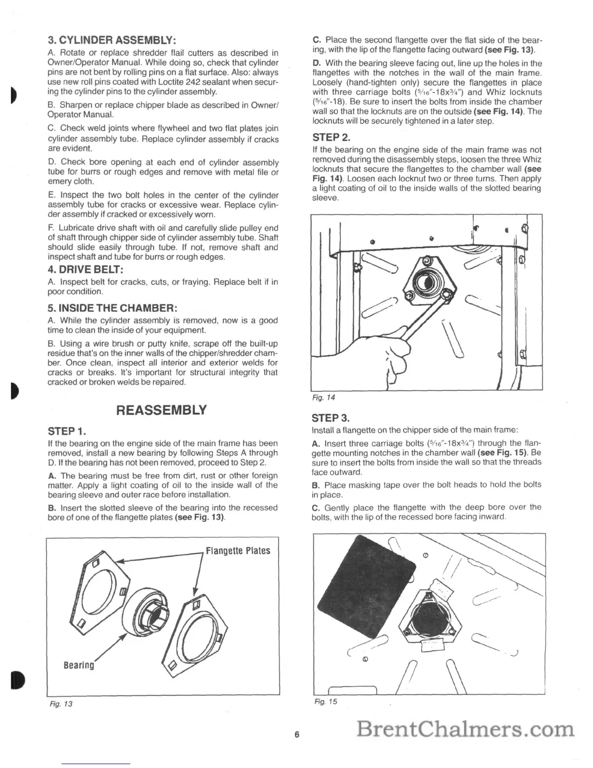
B.
Insert the slotted sleeve of the bearing into the recessed
bore of one of the flangette plates (see Fig. 13).
"-.....01.-------/
Flangette
Plates
Rg. 13
6
C. Place the second flangette over the flat side of the bear-
ing, with the lip of the
f1angette
facing outward (see Fig. 13).
D.
With the bearing sleeve facing out, line up the holes
in
the
f1angettes
with the notches
in
the wall of the main frame.
Loosely (hand-tighten only) secure the f1angettes
in
place
with three carriage bolts
(5/16"-18x3f4")
and Whiz locknuts
(5/
16
"-18). Be sure
to
insert the bolts from inside the chamber
wall
so
that the locknuts are
on
the outside (see Fig. 14). The
locknuts will be securely tightened
in
a later step.
STEP
2.
If the bearing
on
the engine side of the main frame was not
removed during the disassembly steps, loosen the three Whiz
locknuts that secure the flangettes to the chamber wall (see
Fig. 14). Loosen each locknut two or three turns. Then apply
a light coating of oil
to
the inside walls of the slotted bearing
sleeve.
•
Fig. 14
STEP 3.
Install a
f1angette
on the chipper side of the main frame:
A. Insert three carriage bolts
(5I16"-18x3f4")
through the flan-
gette mounting notches
in
the chamber wall (see Fig. 15).
Be
sure
to
insert the bolts from inside the wall
so
that the threads
face outward.
B. Place masking tape over the bolt heads to hold the bolts
in
place.
C.
Gently place the
f1angette
with the deep bore over the
bolts, with the lip of the recessed bore facing inward.
Fig. 15
 Loading...