000000 NEO-M8L - Hardware integration manual
UBX-16010549 - R08 Automotive dead reckoning Page 14 of 28
C1-Public
3 Automotive dead reckoning
3.1 Implementation
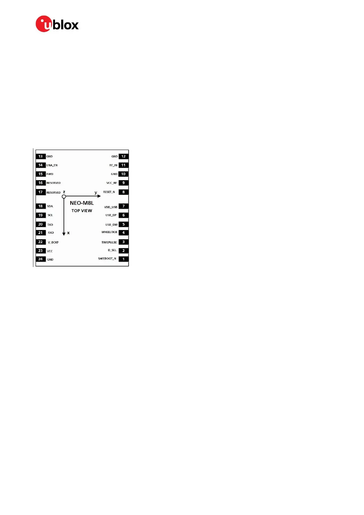
The NEO-M8L 3D dead reckoning modules make use of an internal 6-axis sensor (3-axis gyroscope
and 3-axis accelerometer), meaning that only speed pulse and forward/reverse information must be
provided externally. This can be done by applying speed pulse and forward/reverse signals directly at
the dedicated HW interface pins of the NEO-M8L (see section 1.5) or by transmitting the same
information to the module in UBX-ESF-MEAS messages (SW interface) sent from a host processor to
the module. Where the software interface is used, the customer can re-configure the hardware wheel
tick pin (as EXTINT) to indicate the reference time of the speed and forward/reverse information in
the following UBX message from the processor. Figure 10 shows the orientation of the IMU frame.
Figure 10: NEO-M8L with IMU sensor frame
☞ More information about the ADR functionality can be found in the u-blox 8 / u-blox M8 Receiver
Description Including Protocol Specification [4].
3.2 Sensor calibration
The availability of “Sensor Fusion Mode” dead reckoning depends on the configuration of some
mandatory sensor characteristic data and optional parameter refinements. If only the mandatory
data are provided at installation, the navigation quality may be degraded on first use. The receiver
continuously refines sensor calibration to account for tire wear, temperature and aging. Data from
continuous calibration are stored for future use in non-volatile memory.
☞ For more information about mandatory, calibration and optional configuration parameters, refer
to the ADR configuration section of u-blox 8 / u-blox M8 Receiver Description Including Protocol
Specification
[4].
☞ Note that the performance of the ADR solution relies on stable sensor location and orientation
with respect to the vehicle frame. The module must be mounted securely within the vehicle.
3.3 Software migration
☞ For an overall description of the module software operation, see the u-blox 8 / u-blox M8 Receiver
Description Including Protocol
[4].

 Loading...


